When designing a superheterodyne receiver, terminating mixers properly is important. This is especially important for the second mixer which is responsible for converting the intermediate frequency (IF) into audio. Even at this stage of the circuit, maintaining a consistent 50 Ω termination across all frequencies is required to minimizing distortion products and maintain a high dynamic range.
To meet this strict impedance requirement, a combination of audio diplexer and a common base amplifier can be used. Common base amplifiers naturally provide a low input impedance for the desired audio frequencies. Meanwhile, the diplexer routes all other frequencies into a dedicated 50 Ω termination resistor. Working together, these components ensure the mixer always sees a constant load across the entire frequency spectrum.
Design and Simulation
The diplexer was designed using the Marki Microwave LC filter design tool. Using a low-pass high-pass configuration, the target cutoff frequency was set to 110 kHz.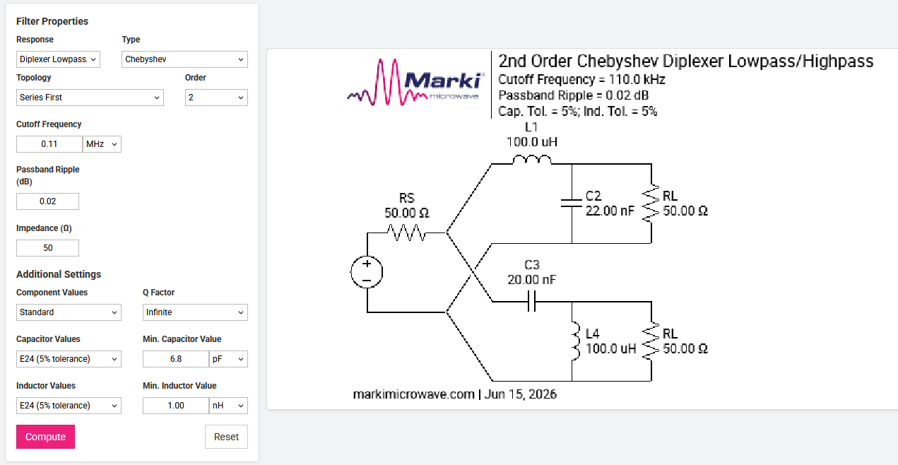
The common base amplifier was designed with a gain of approximately 20 dB and an output impedance of 1 kΩ. With an MMBT3904 BJT at a quiescent current (Ic) of 6 mA, the amplifier exhibits an intrinsic input impedance of roughly 4 to 5 Ω, which was increased to 50 Ω by placing a 47 Ω resistor in series with the input.
A simulation of the circuit was made in LTspice.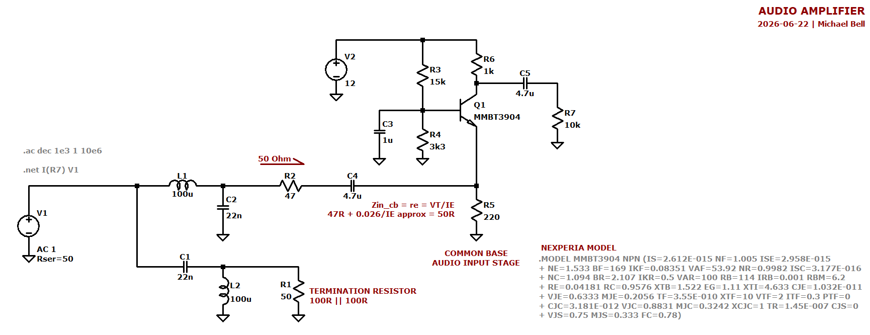
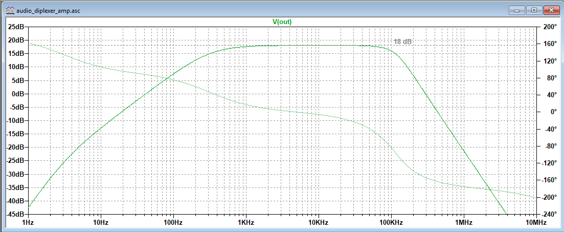
From the simulation results, the passband is flat with a gain of 18 dB. The low frequencies begin rolling off at 200 Hz, and the high frequencies begin sharply rolling off at 110 kHz as designed.
Designing & Fabricating the PCB
The PCB was designed in KiCAD, focusing on minimizing the physical footprint while restricting all routing to a single layer. Utilizing some custom footprints for through hole components to be suface mounted, the overall footprint was 30 mm x 20 mm.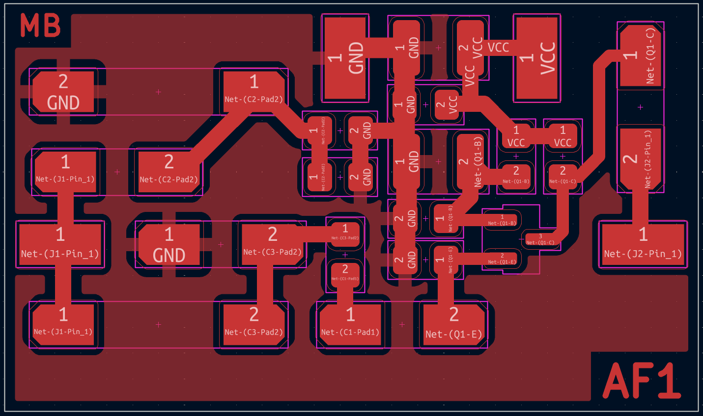
To fabricate this PCB, I utilized the toner transfer method of masking a blank copper clad board.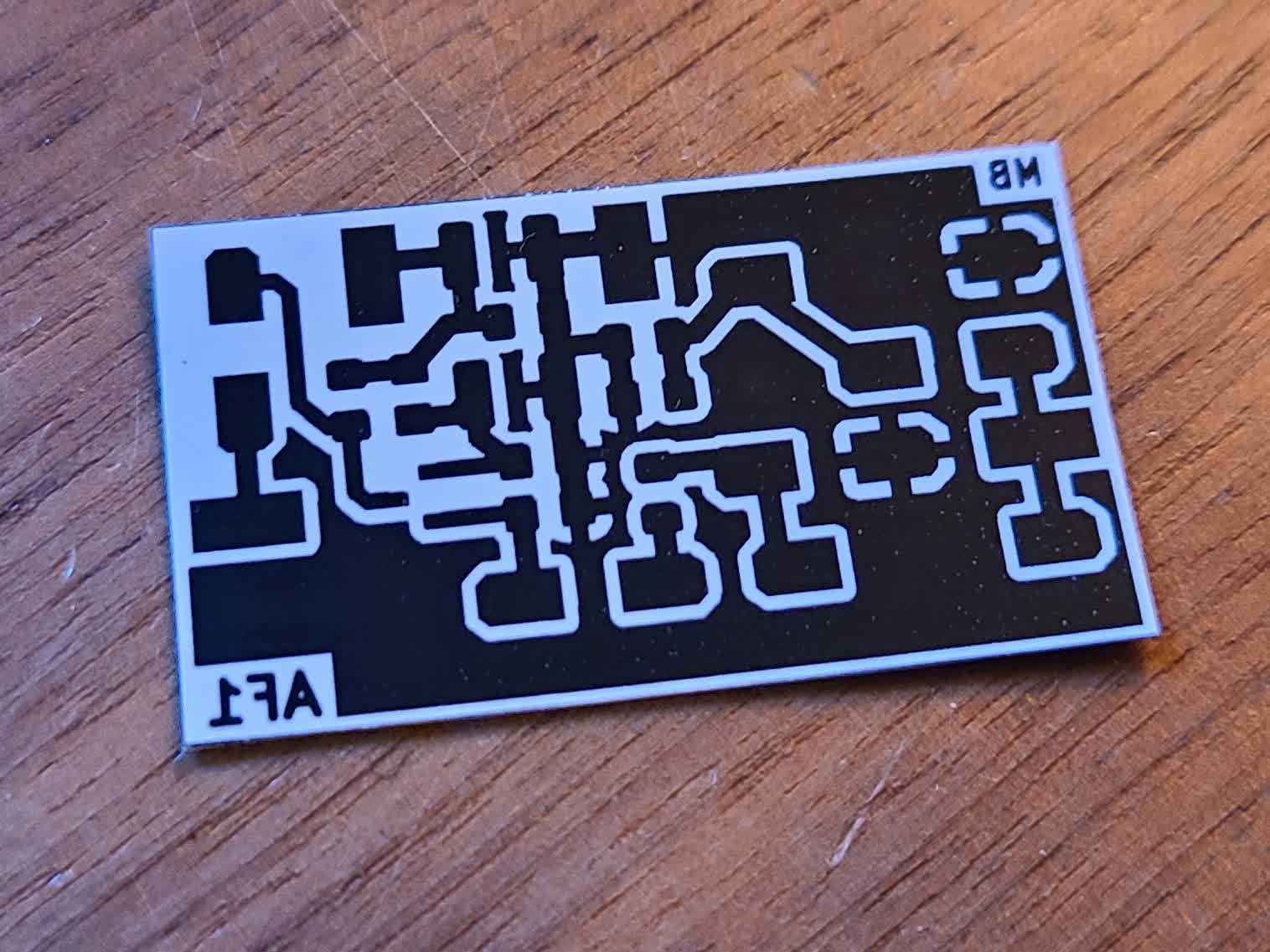
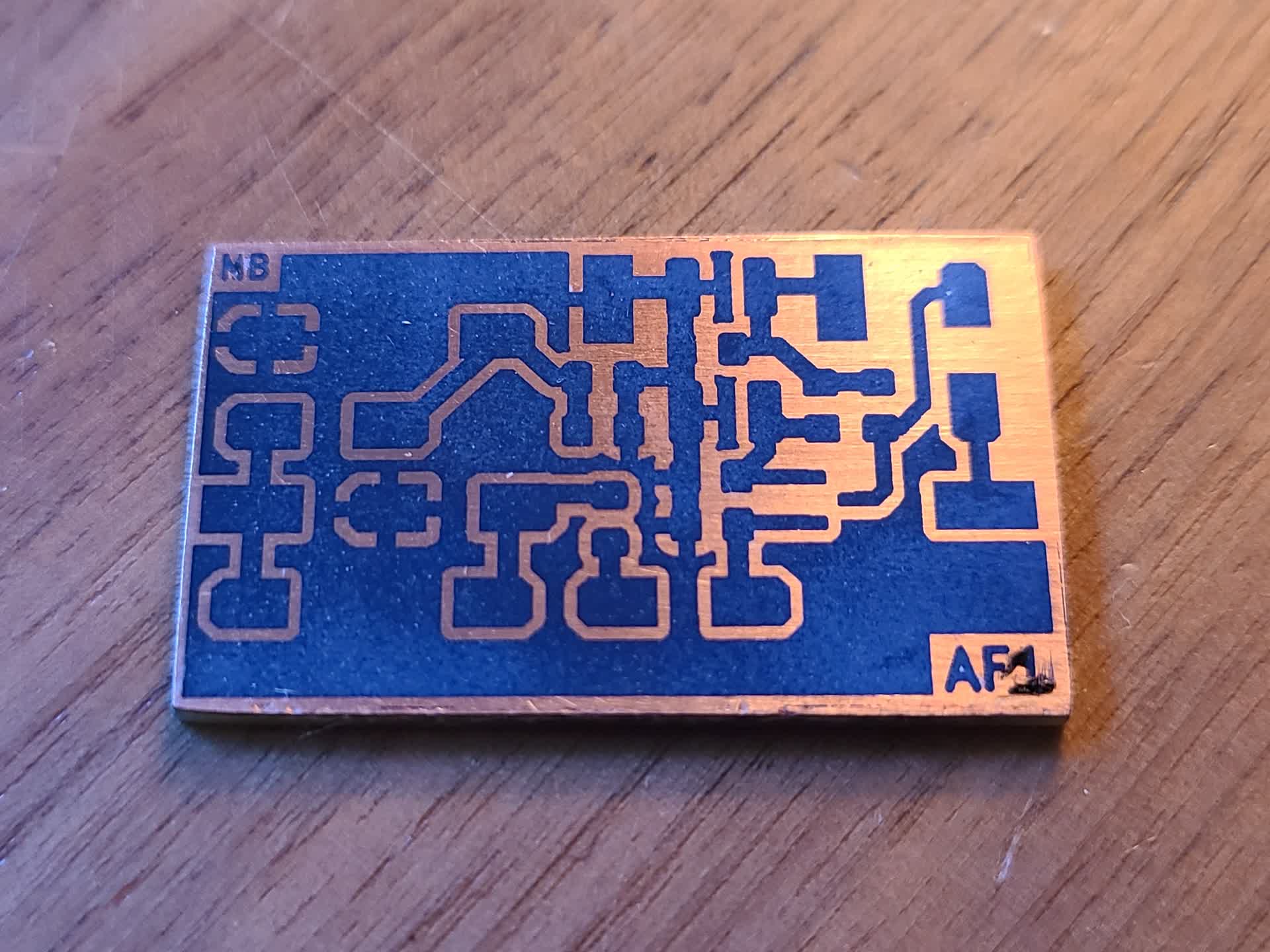
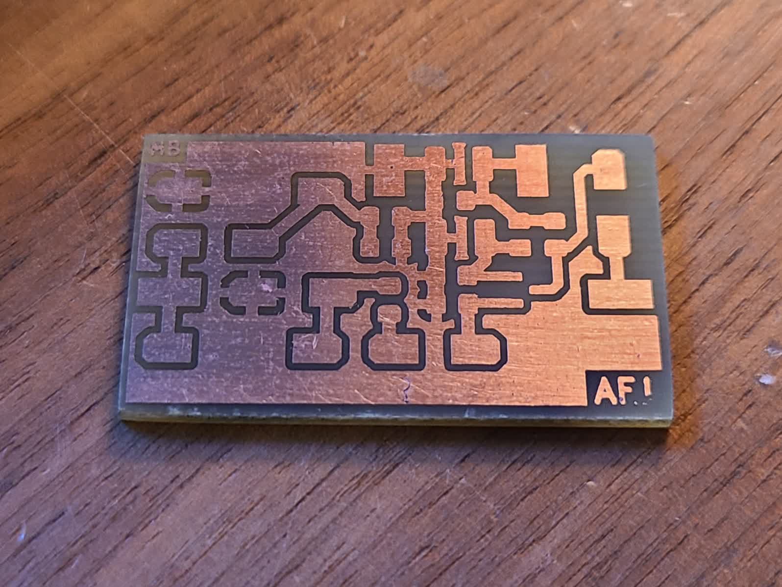
I then used ferric chloride etchant to remove the unmasked copper.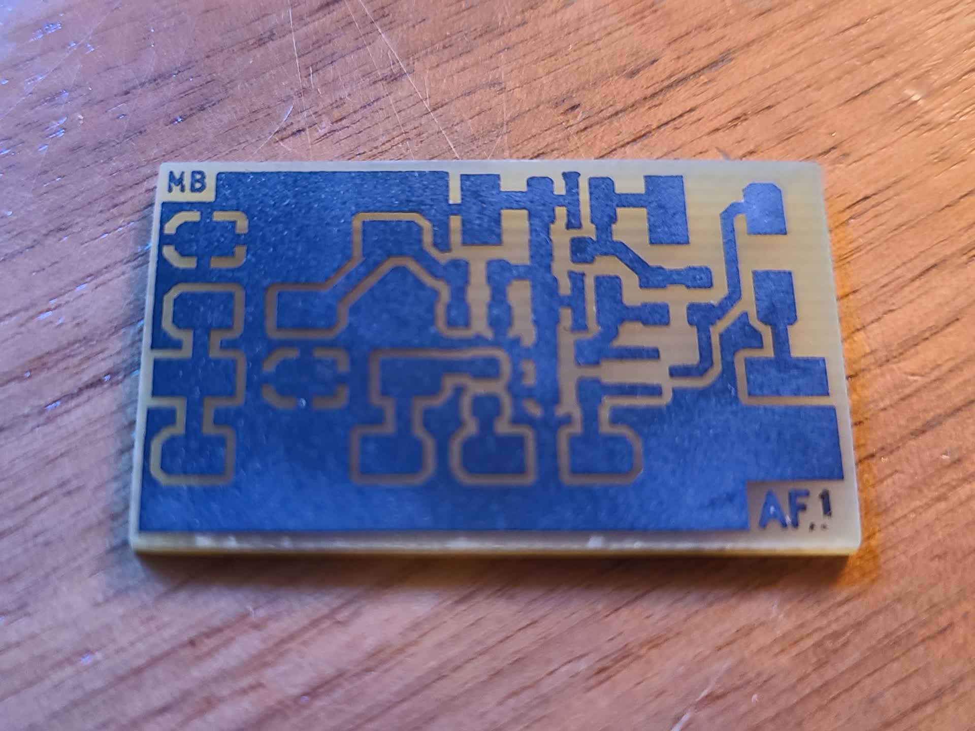
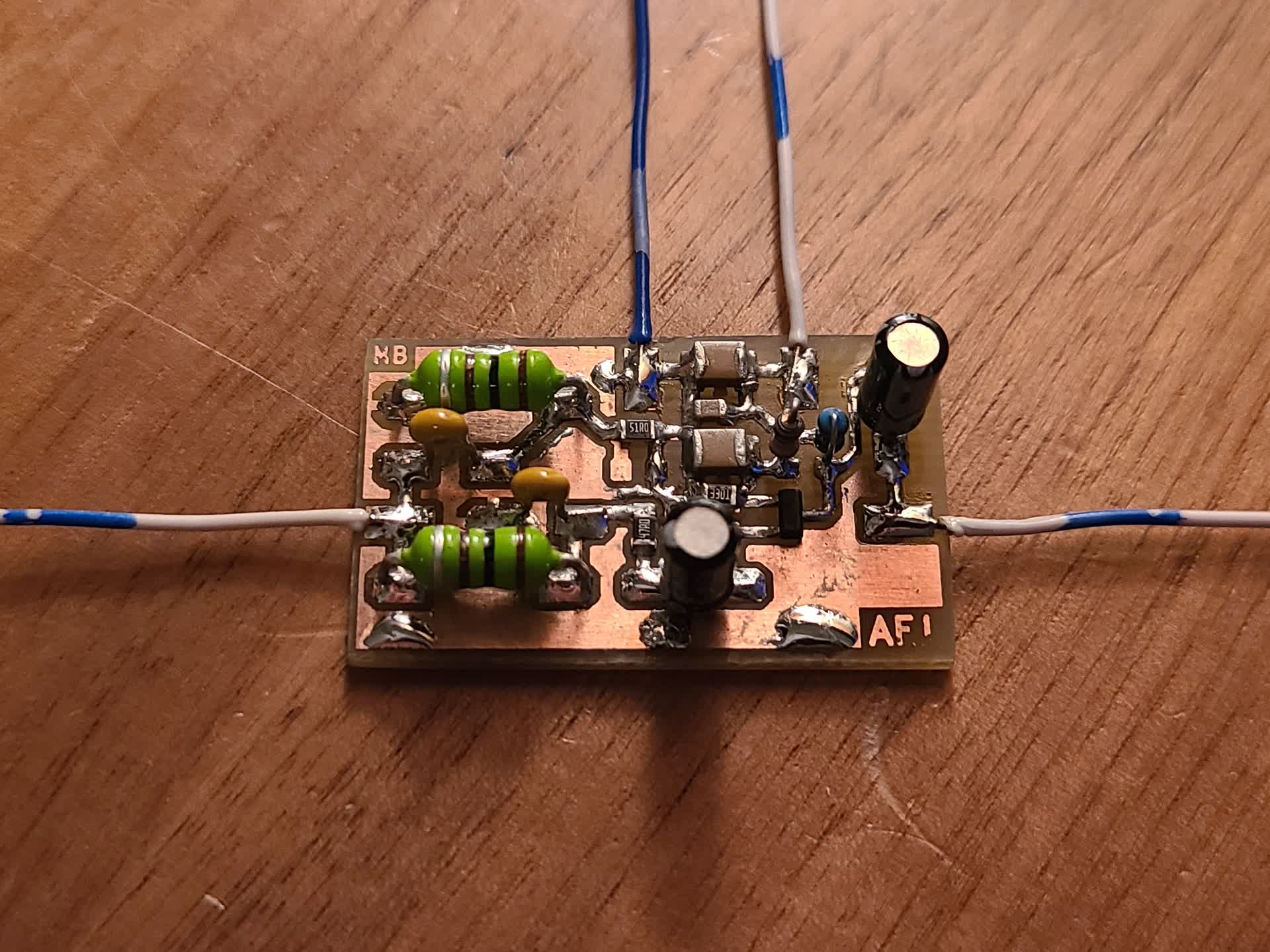
Assembling the PCB
Using components I had oh hand, I assembled the board.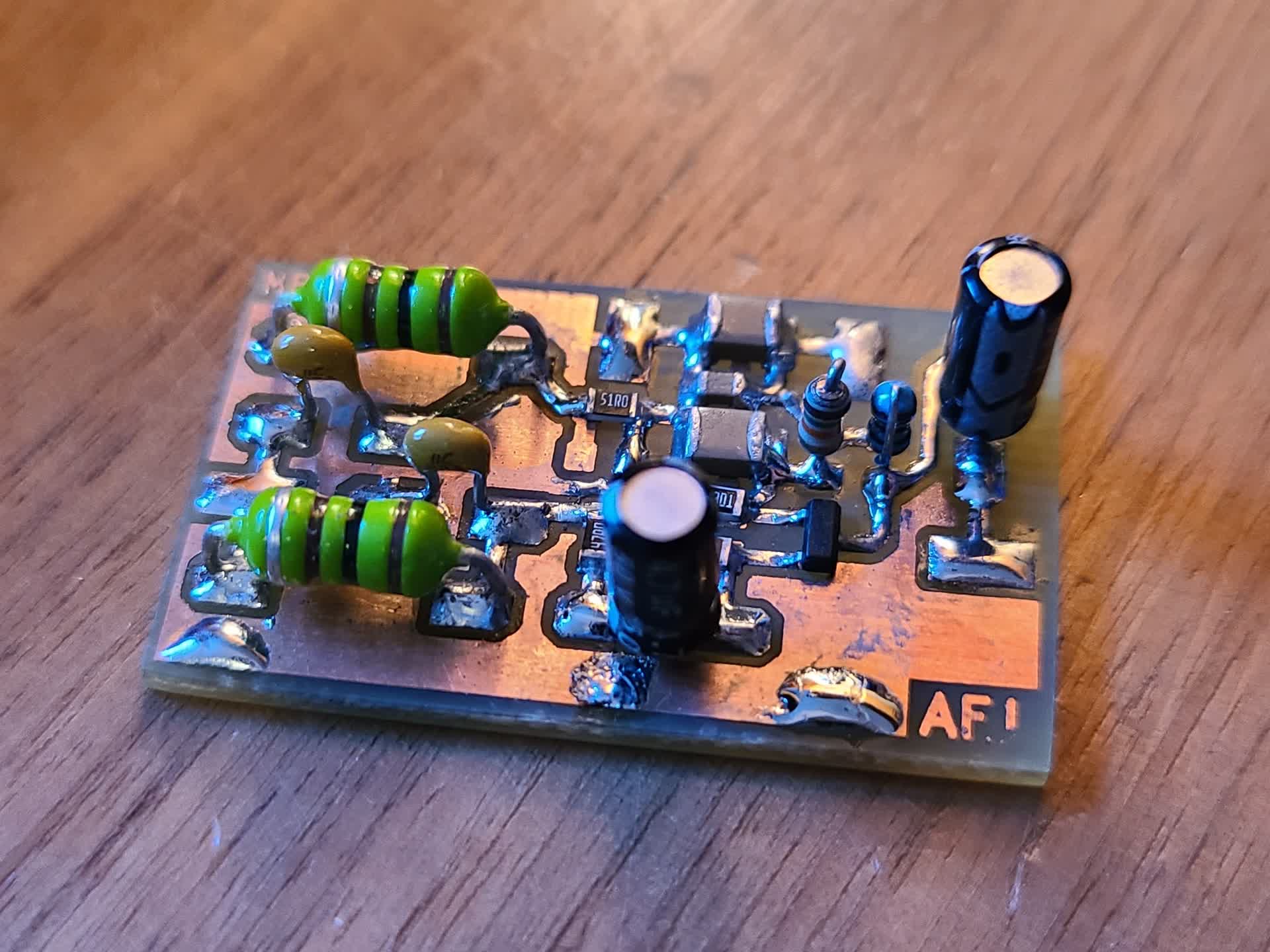
Testing the Amplifier and Diplexer
To test the amplifier, I used my function generator and oscilloscope. I tested frequencies from 100 Hz to 1 MHz with an input power of around -20 to -10 dBm. Using the oscilloscope I measured both the input and output voltages to calculate the voltage gain of the amplifier.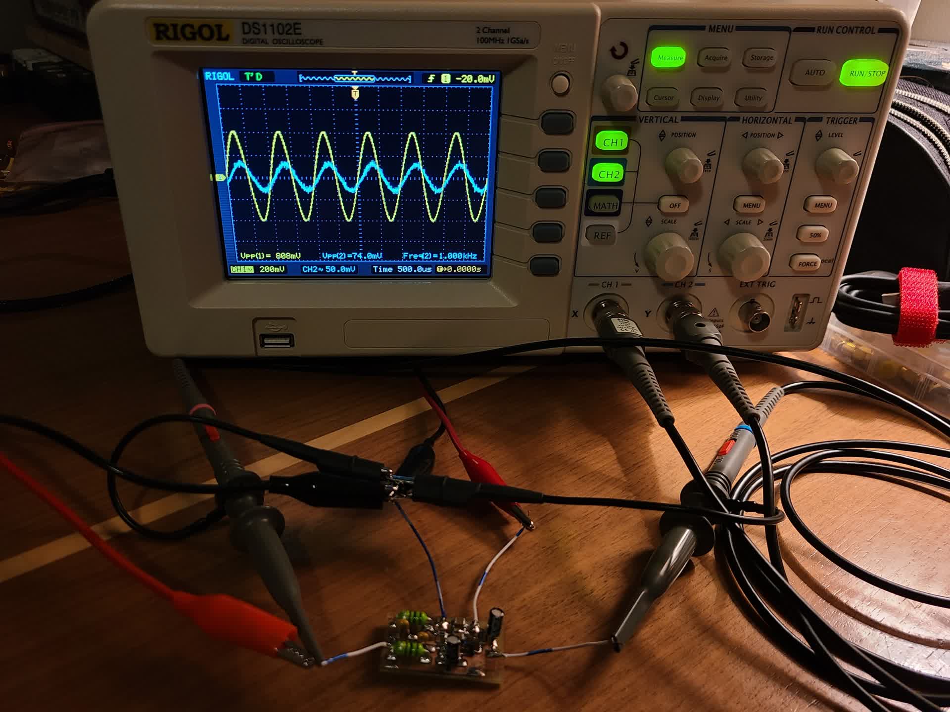
The test results were very similar to the simulation, with the light rolloff at the low frequencies, and the much steeper rolloff at 110 kHz.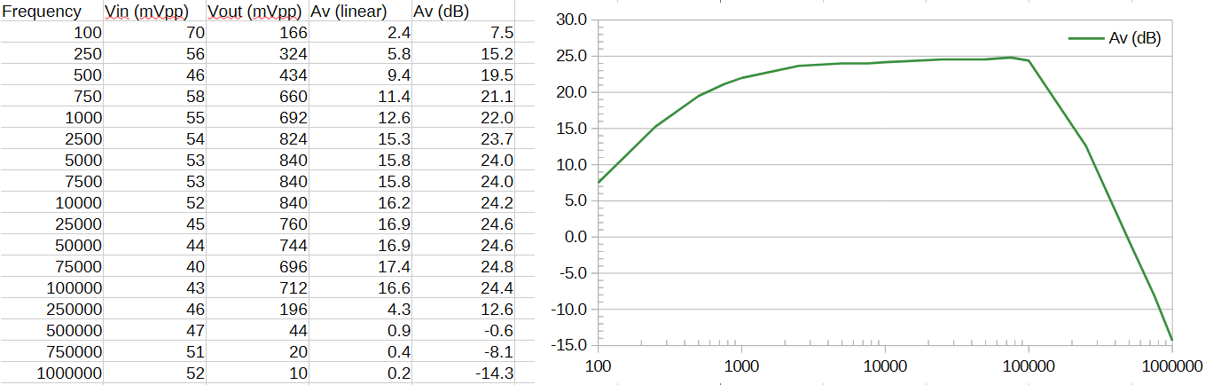
I then used a NanoVNA to test the input impedance from 500 kHz to 30 MHz.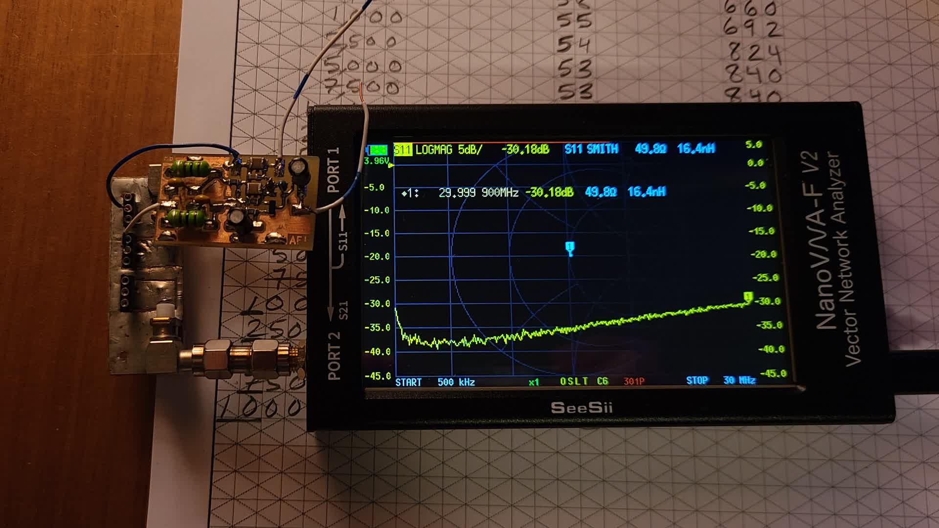
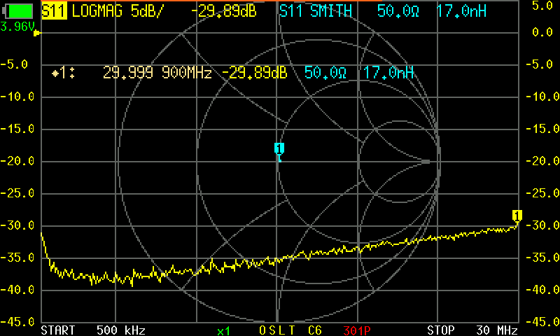
As designed, the input impedance is a constant 50 Ω across the HF band.
Remarks
The amplifier produced a flat 24 dB of gain in the audio band given a 1 MΩ output load (which will likely be in the 100's of kΩ in the final receiver). The input impedance was proven to be constant at 50 Ω across the HF band frequencies, which should play nicely with the mixer.