To prevent any strong out of band signals from overloading the frontend of my reciever, I designed a bandpass filter to place before the rf amplifier.
Utilizing a common design known as a capacitor coupled resonator banpass filter (BPF), I designed a 2 resonator BPF. This was designed twice, mainly because I utilized a poor inductor core material in the first design.
This project took a little longer than anticipated, but it was due to an error that put me on track to learn a lot about the choice of a good inductor core material.
I will start with the good design, then go over what I did wrong the first time.
The Successful Design
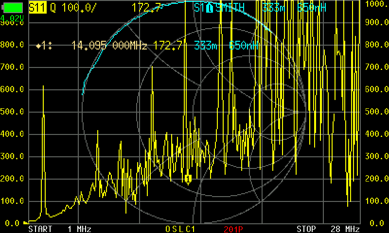
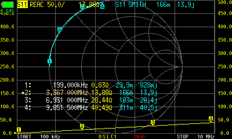
After learning where I went wrong in my initial design, I looked through some of my spare toroid cores and found a suitable core by winding a couple turns of wire around them and testing them with my NanoVNA. The core material I settled upon is still a mystery to me, but the Q-factor I was able to achieve at my frequency of operation was fairly decent.
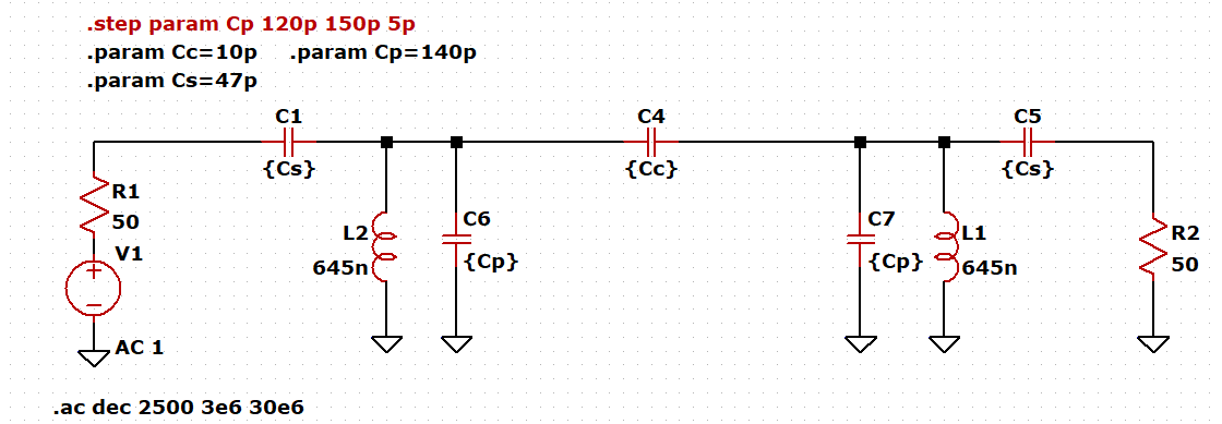
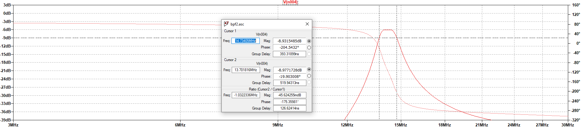
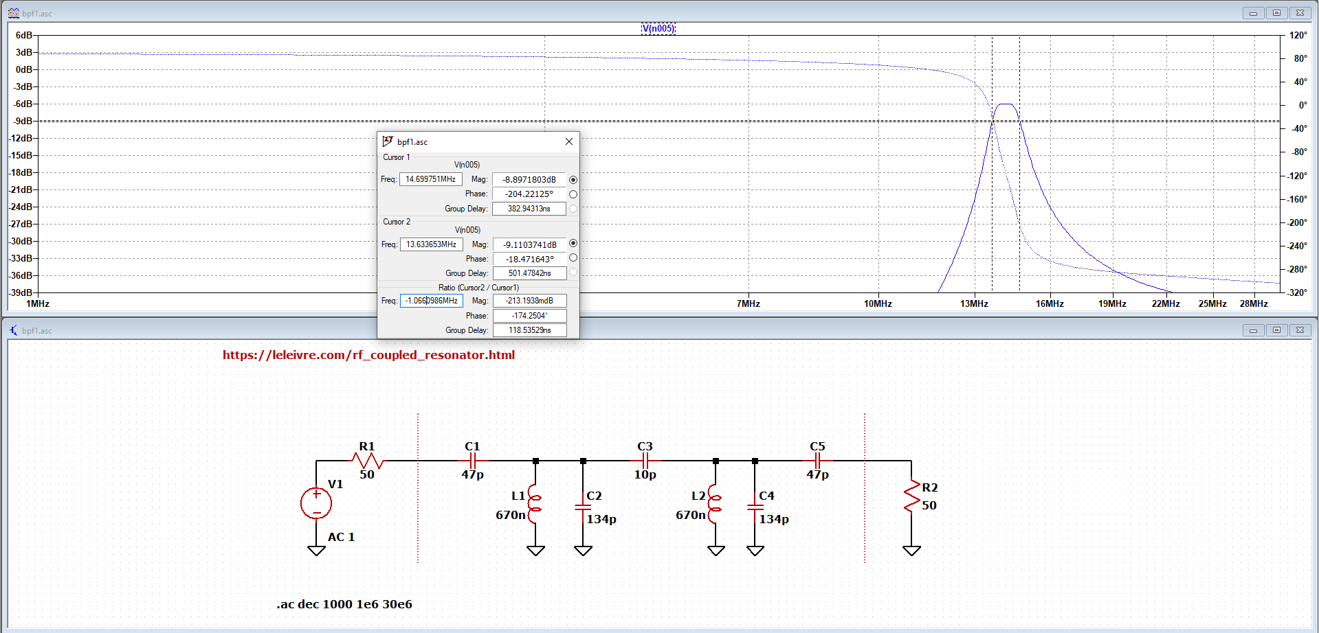
For calculating the component values, I opted to use an online calculator (LeLeivre RF Tools) since it streamlined the process and made protoryping fast. Of course, like all other online calculators, I verified the outputs by simulating the AC response of the filter values this site gave me.
After the first design, I once again began by re-calculating the values I needed for the filter: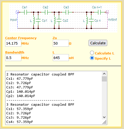
Making and Measuring the Inductors
Now, taking the newly found cores I wound 13 turns of 24 AWG which got me to around 650 nH at 14 MHz.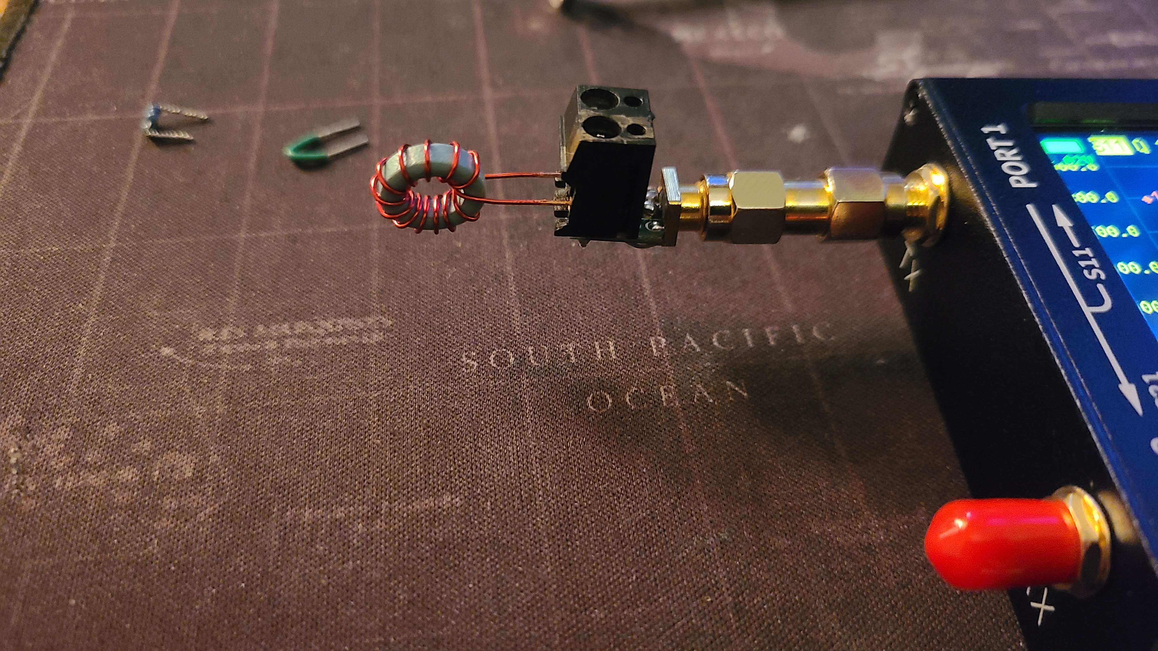
Building & Testing the Filter
After winding and testing the inductors, I built the filter on a piece of copper clad board. I used some trimmer capacitors to further fine tune the circuit once it was built.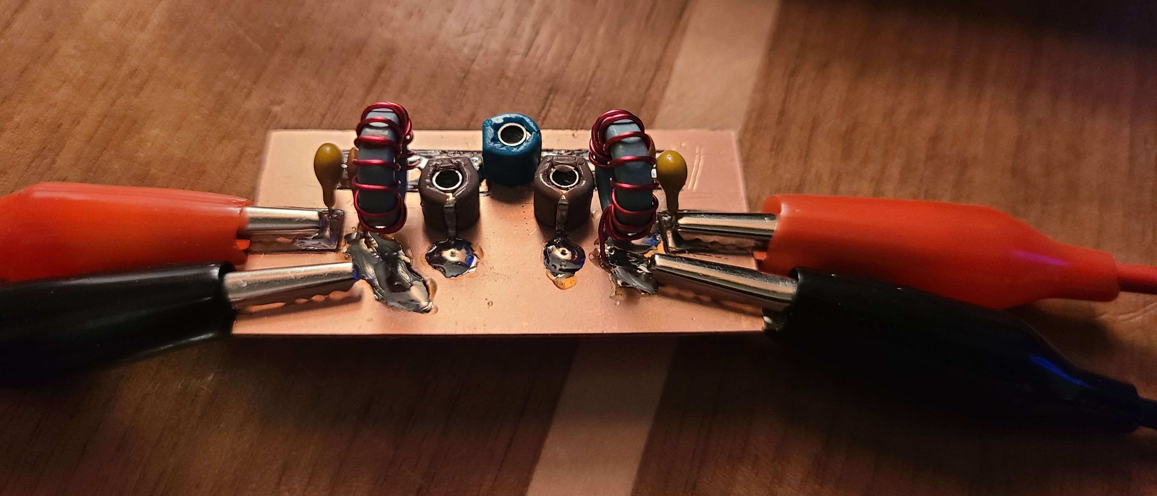
After testing I was very happy to see that the bandwidth is very close to what I wanted, and with very little need for tuning the coupling capacitor, the insertion loss was only 1.2 dB.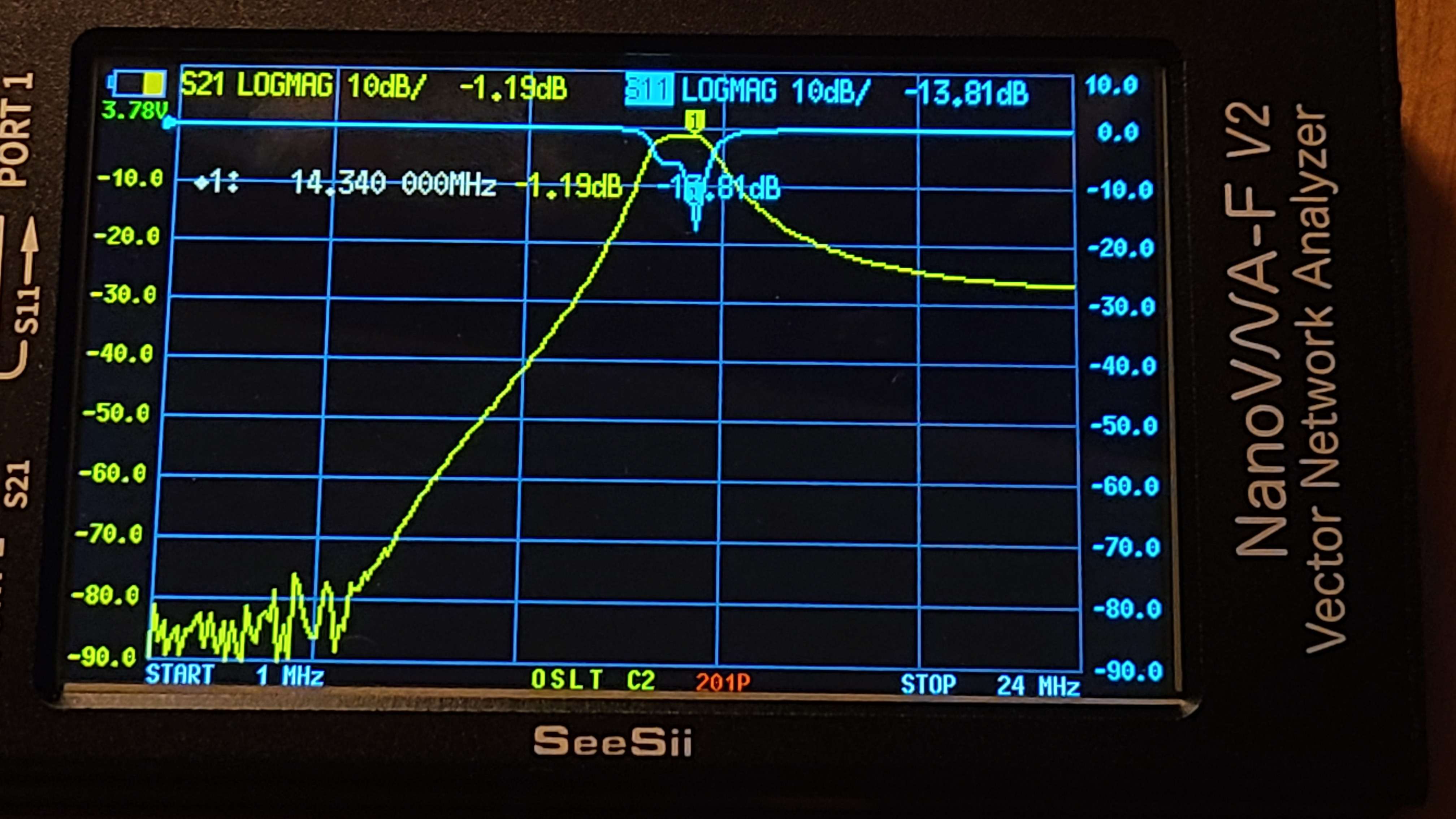
The Unsuccessful Initial Design
Inputting my parameters into (LeLeivre RF Tools), I got the following results.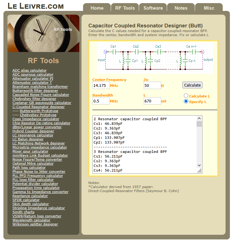
Making and Measuring the Inductors
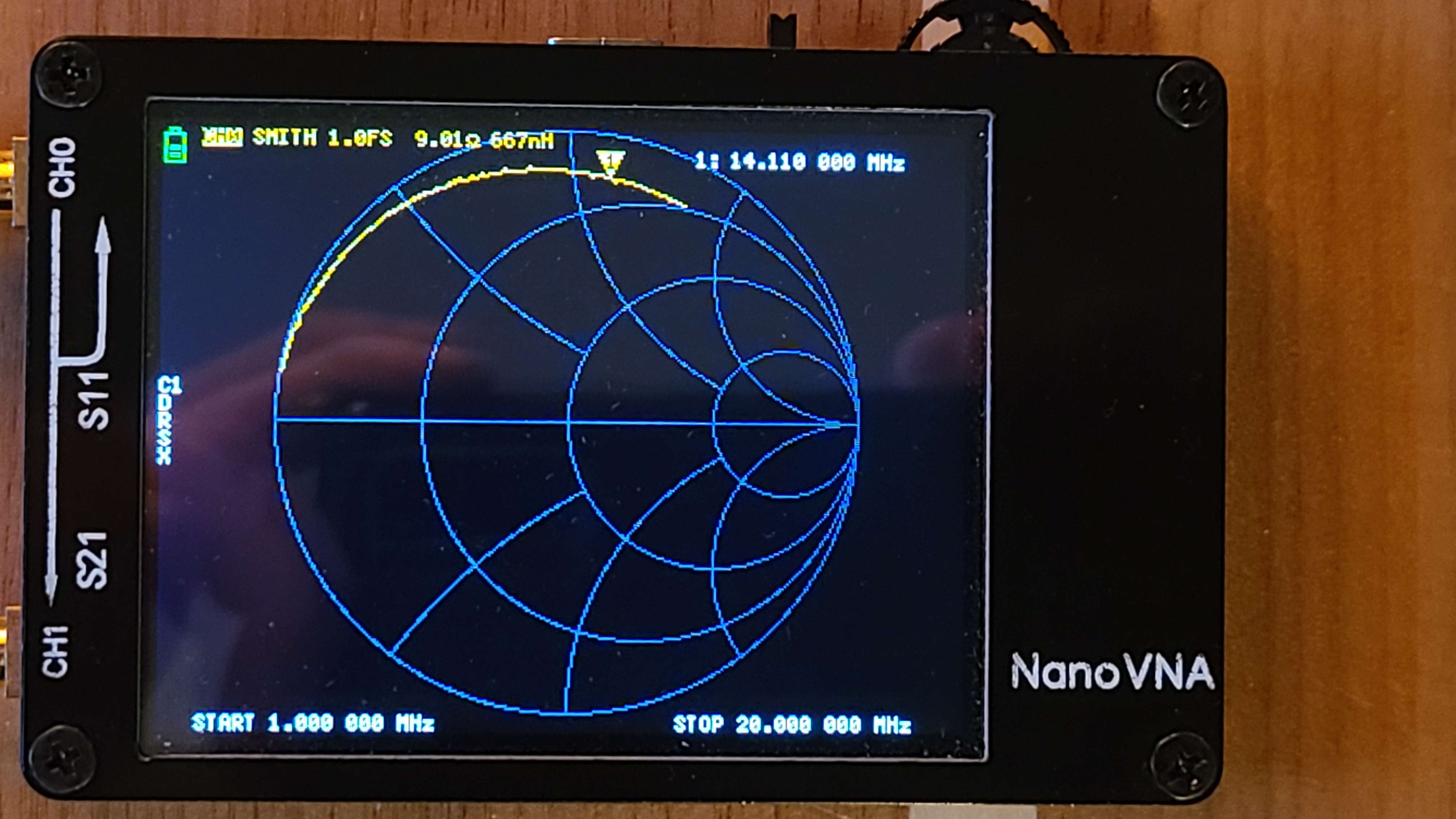
Using T37-2 Toroids as the inductors core, I wound 24 AWG around the toroids to acieve an inductance of 670 nH (at 14 MHz).
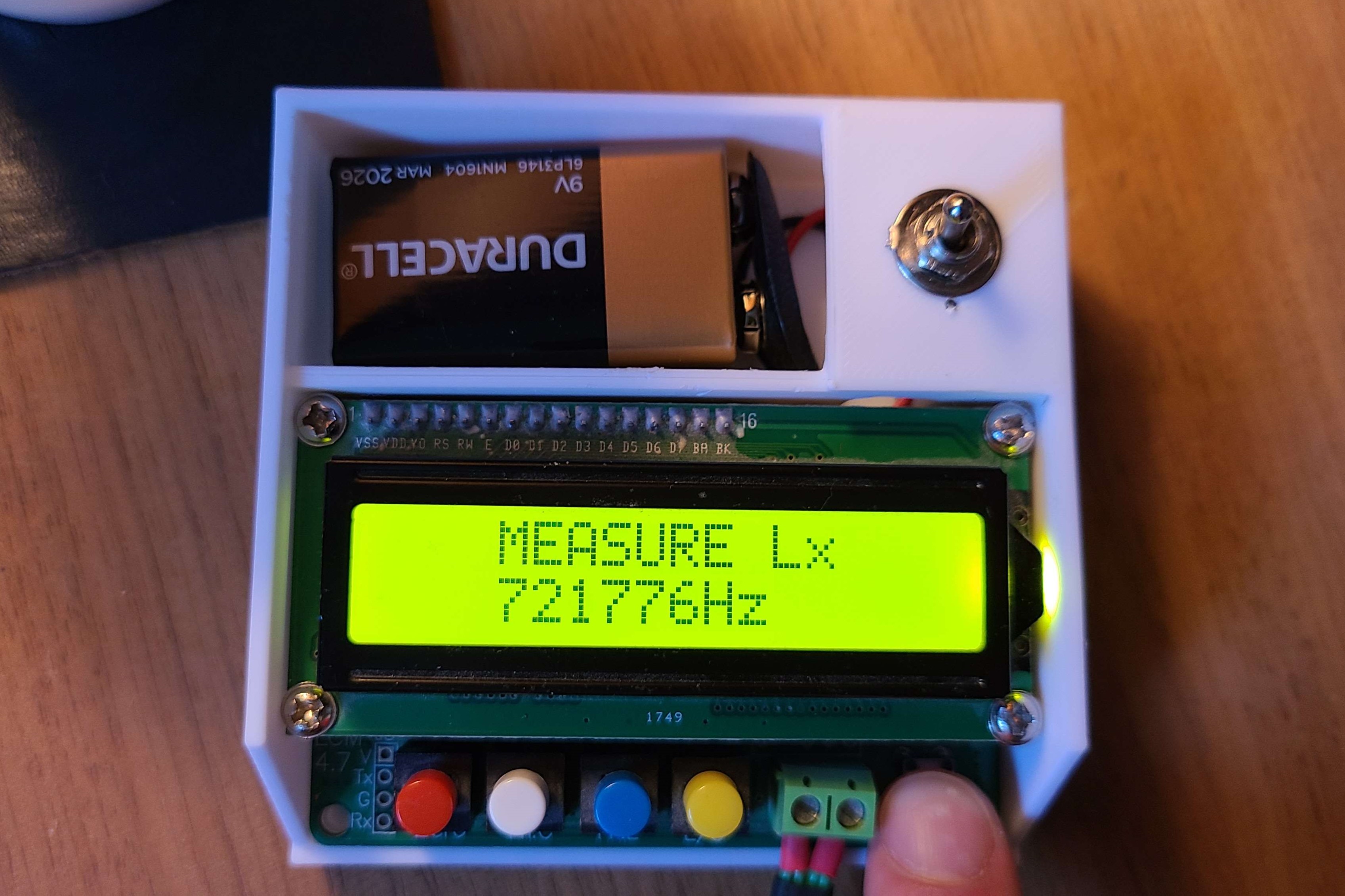
Measuring the inductance with my LC-meter, I measured 737 nH at 721.8 kHz. Using my NanoVNA I measured 667 nH at 14.110 MHz, which was practically spot on.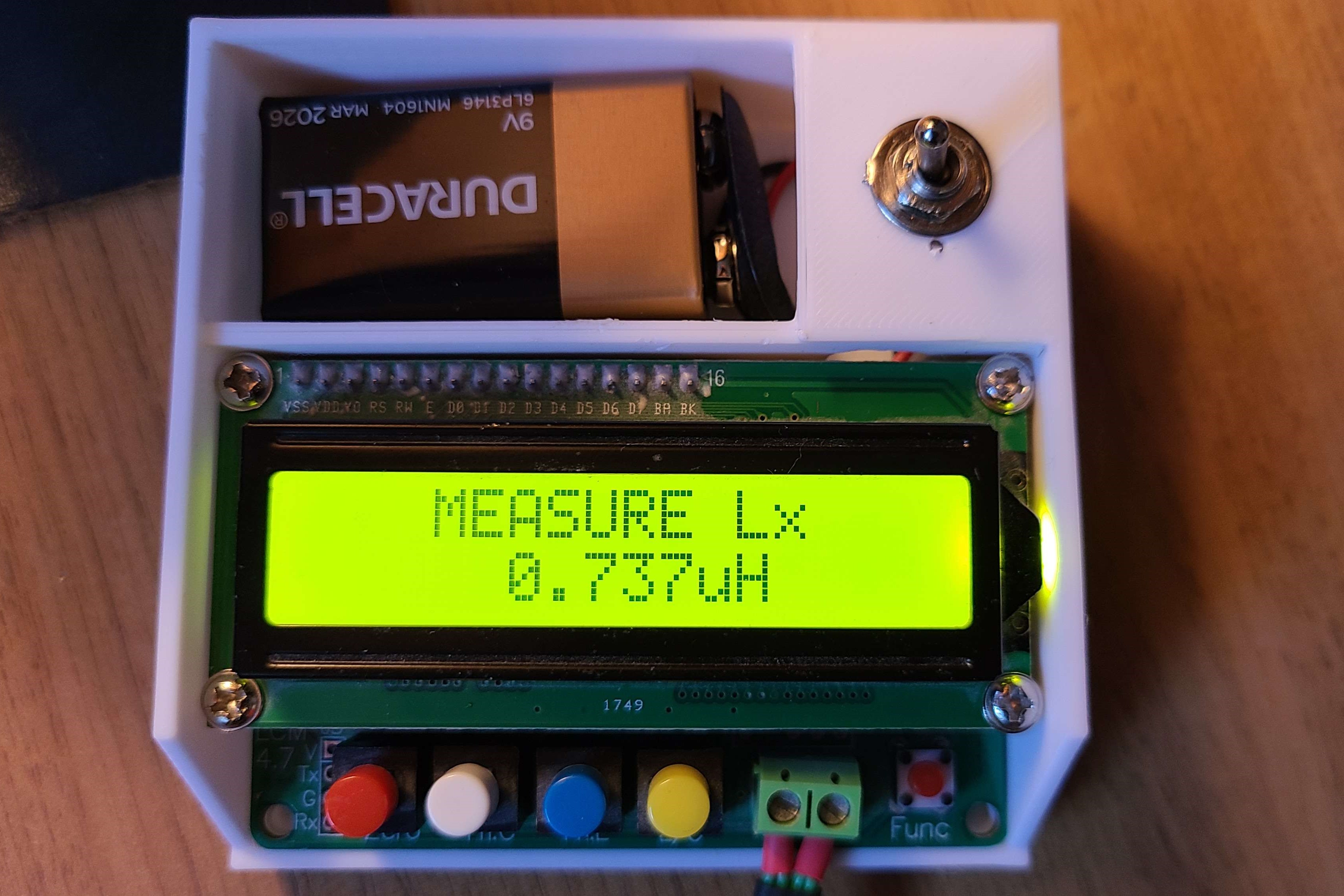
Building & Testing the Filter
Building the filter was straight forward. I soldered everything to a piece of copper clad and included trimmer capacitors to further tune the filter once it was built.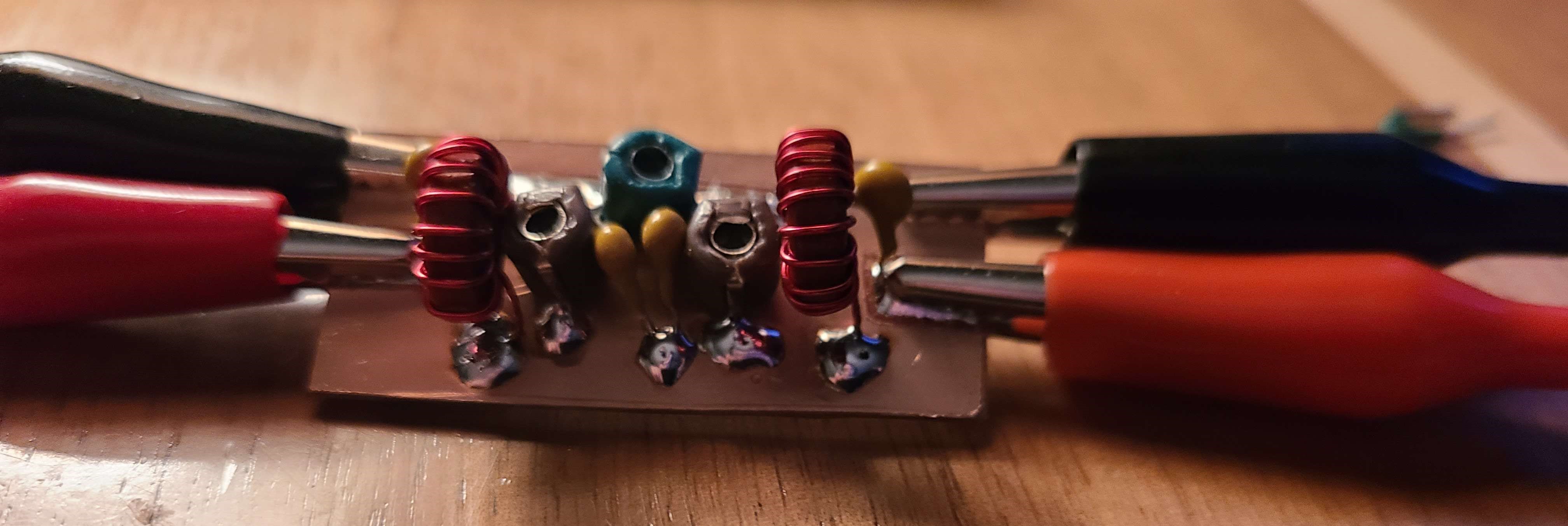
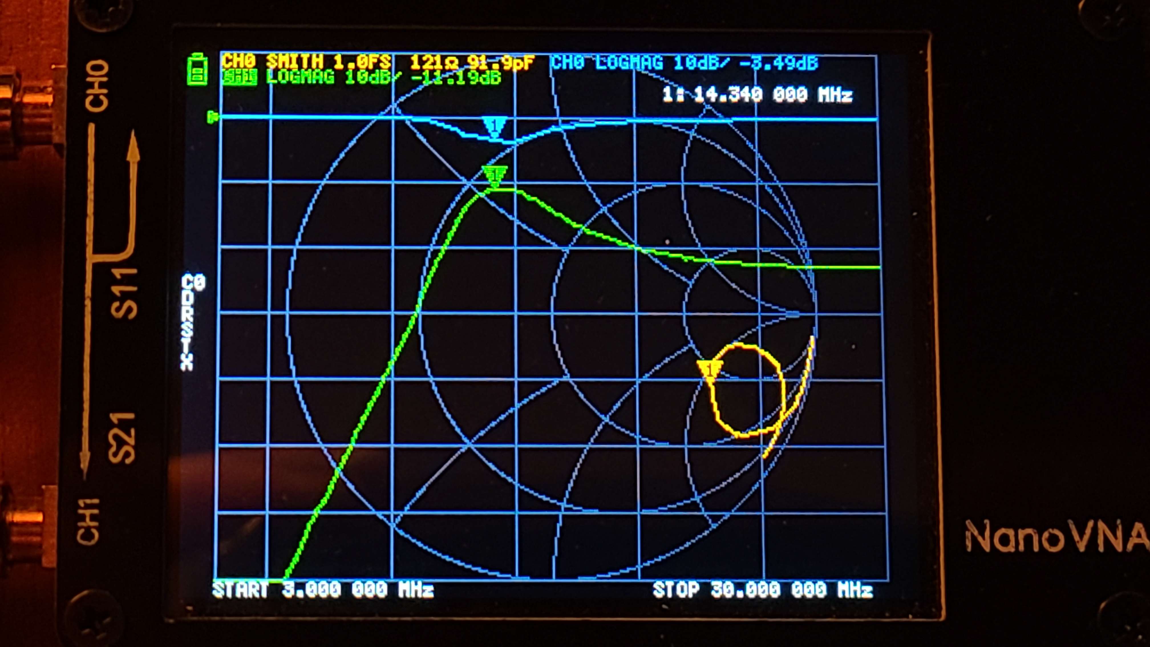
To test the filter I set my NanoVNA up to measure the S21 behaviour. However, the results from the S21 measurement were extremely dissapointing. An insertion loss of 11 dB is not good at all.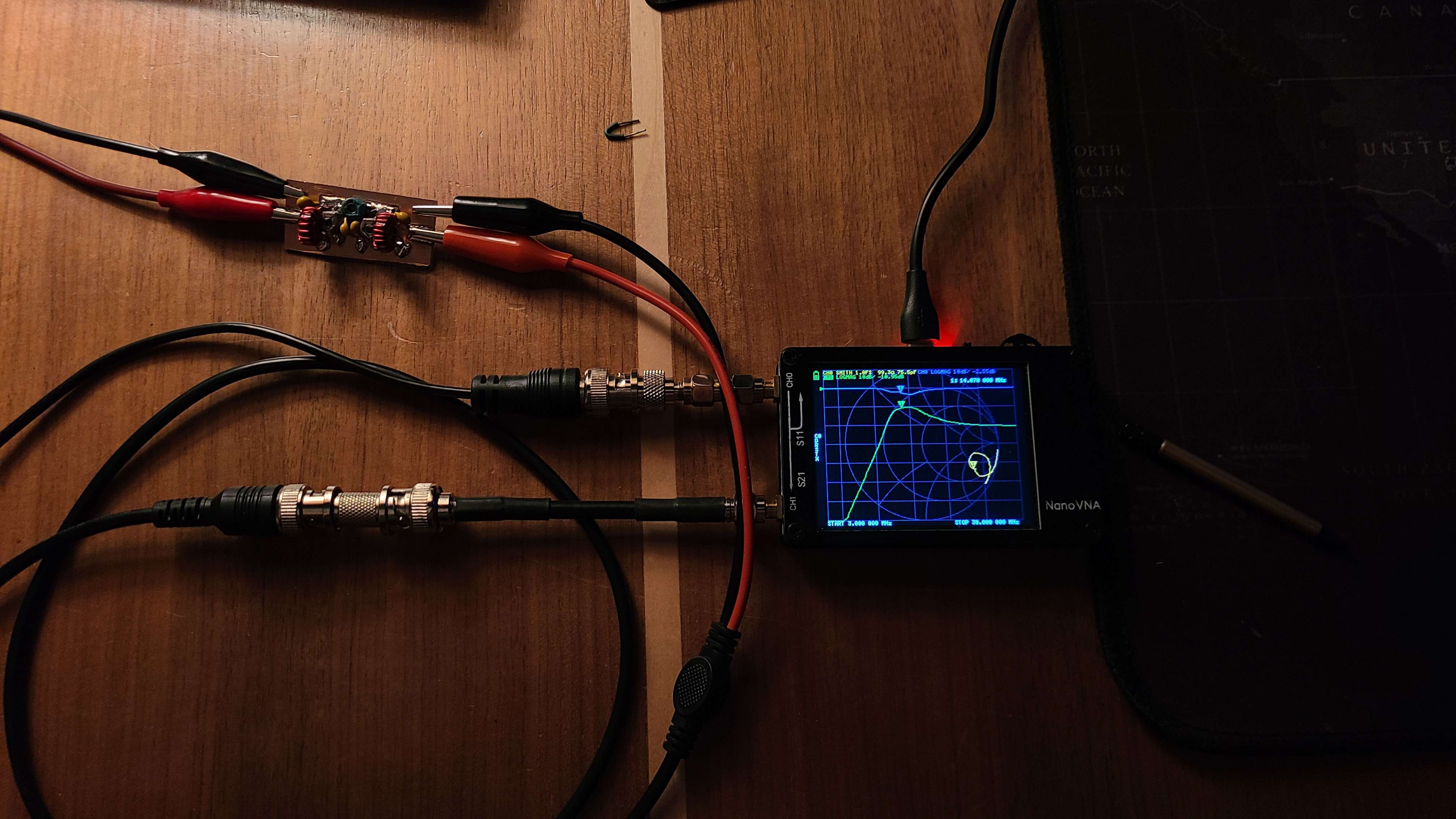
Takeaways and Lesson Learned
What I learned with and after this failure:
- Inductor Core material matters significantly.
- Ferrite and Iron Cores have frequency ranges that they operate with a high Q.
- The meaning behind an inductors (and capacitors) Q factor.
- The cores I chose were only good for 100 kHz to 1 MHz.
The biggest takeaway for me was learning about how to properly determine if an inductor is good. This means understanding what the Q factor really means. A simple way to put it is the Q factor is the ratio of stored energy to lost energy, or reactance/resistance. If you have a low Q, that means the inductor (and/or it's core material) is very lossy.
Remarks
After learning more about inductor core material selection and inductor Q factor due to this project, I was able to come out on the other end with a functional (and fairly low loss) bandpass filter. This filter will sit between the antenna input and low noise recieve filter on my superheterodyne radio project.