When testing the 20m superheterodyne reciever, there was a lot of noise generated by the previous frontend amplifier design, so I have decided to re-design the frontend amplifier. In this approach, I utilize the cascode configuration.
Amplifier Design
The amplifier was in the cascode configuration. With a BFR193 NPN BJT and the jelly-bean 2N3904 NPN BJT, I designed the amplifier to have a gain of around 25dB.
The amplifier was designed to have a quiescent current of 10mA. Both the input and output impedances were matched based on calculations and verified using the simulation.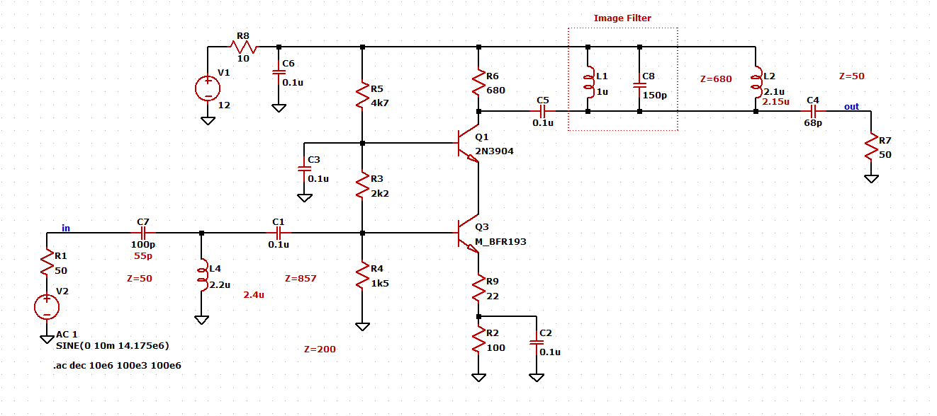
Building the PCB
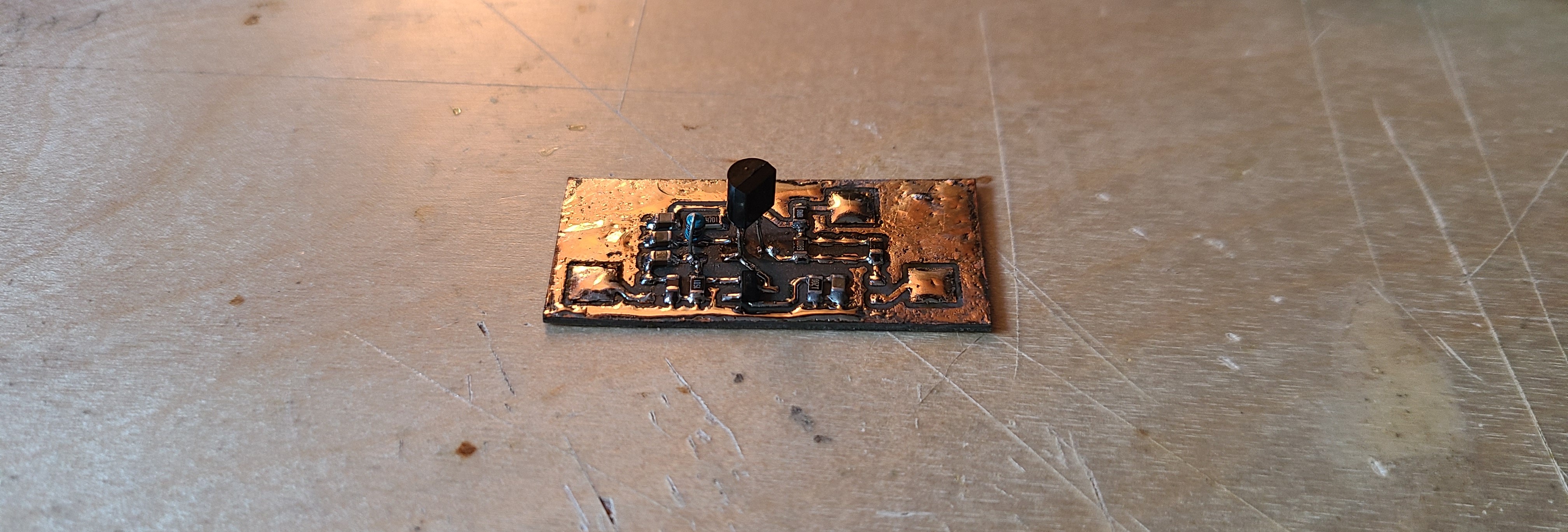
The PCB was designed in KiCAD and etched onto a piece of scrap copper clad board. Components used were surface mount, except for a few through hole components I needed to use.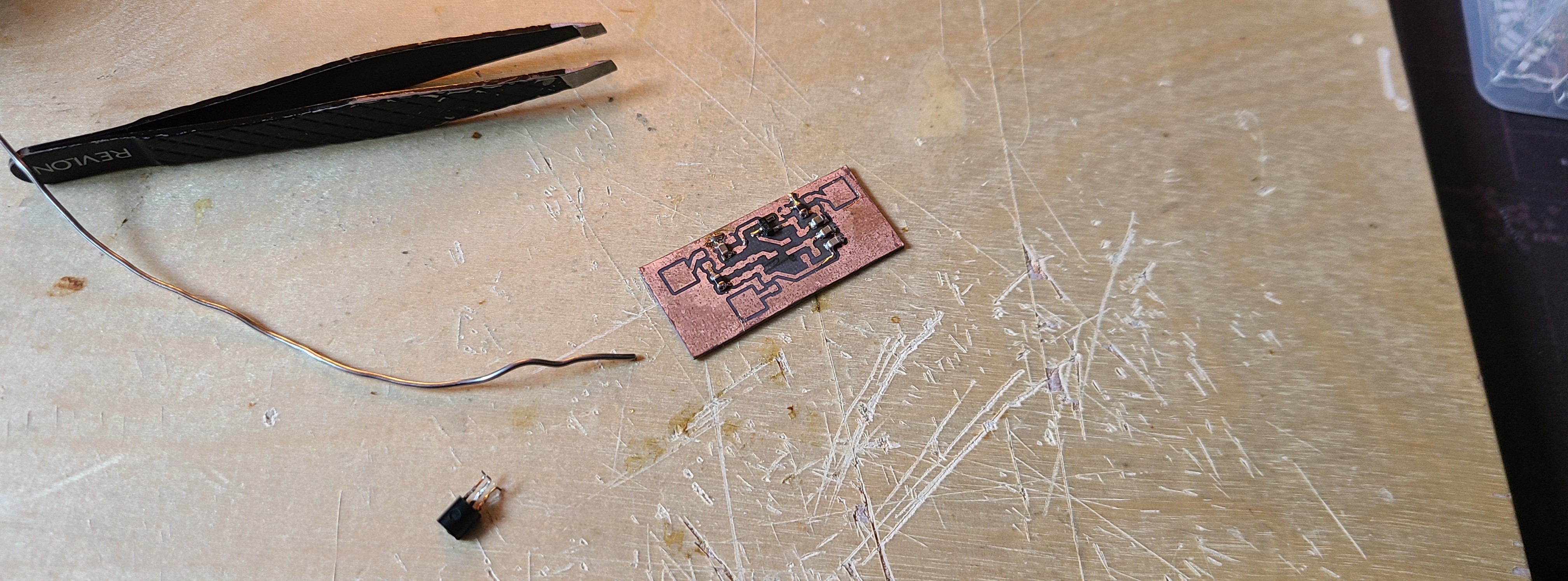
Testing
The amplifier was tested using the NanoVNA-F V2. By calibrating with two series attenuators on port 2 of the device I am able to measure the S21 Logmag without damaging the device, but miss out on the S21 impedance measurement of the amplifier.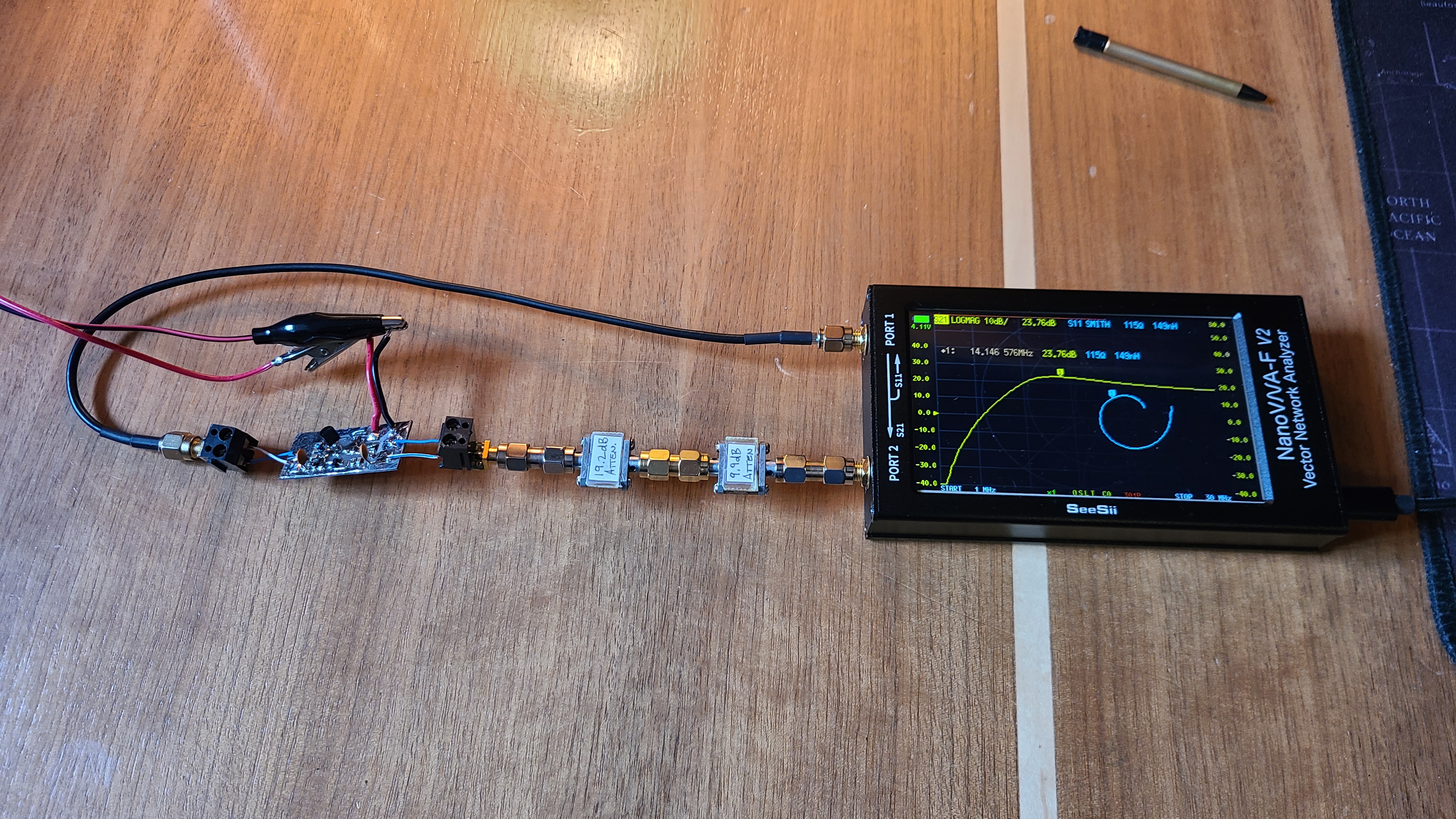
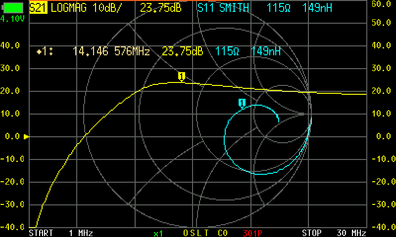
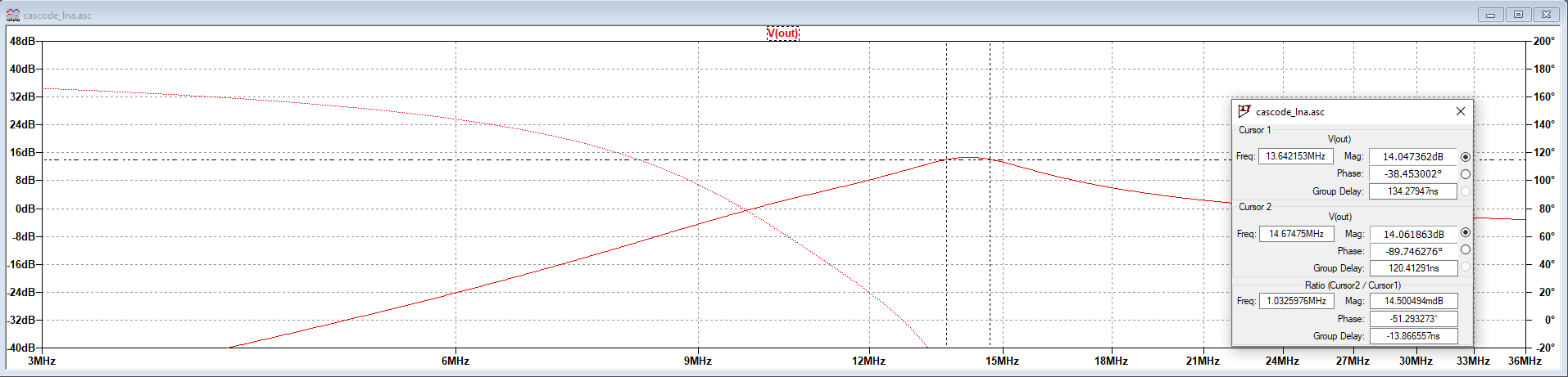
Upon first connecting the amplifier, I noticed the input impedance was off, by more than 2 times. So I redid the simulation and fixed the impedance matching network to get as close to 50 ohms as possible.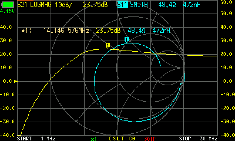
The results were as expected after fixing the circuit.
Remarks
The amplifier worked well, but I am learning that having so much frontend gain is affecting everything downstream, especially when it comes to noise. By reducing the gain and looking into lower noise components, I may be able to improve this.