To effectively build a Crystal filter, I characterized the new 4 MHz crystals I ordered. Using two methods, the NanoVNA-H with DiSlord firmware, and the G3UUR method.
Characterizing Crystals
Holder Capacitance
The holder capacitance was measured using an LC-100A inductance-capacitance meter. The resolution is adequate, but not the greatest tool for the job. I was able to get an accuracy close to 0.1 pF. The LC-100A operates by measuring the change in frequency of an oscillator upon the addition of a capacitor or inductor. The frequency of measure was around 750 kHz.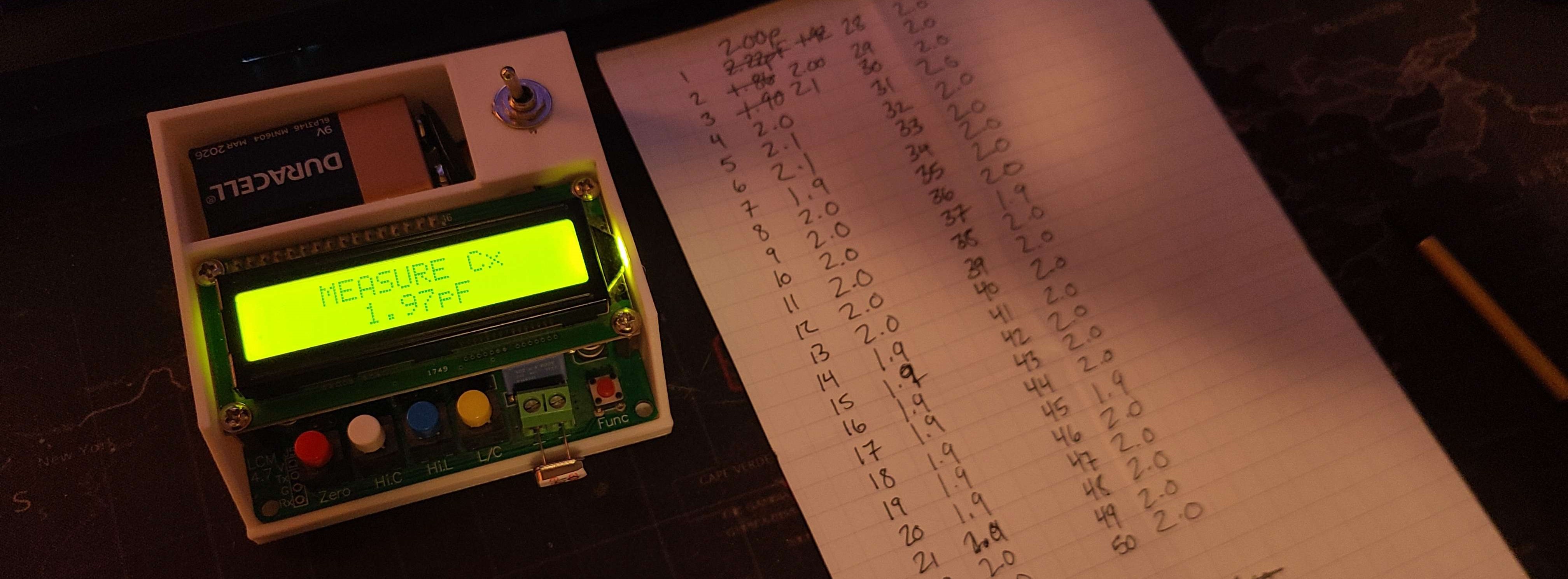
NanoVNA-H (DiSlord v1.2.40 FW)
Using the NanoVNA-H DiSlord firmware v1.2.40, I utilized the internal crystal characterization function and set the VNA to have a very fine frequency step. Focusing on the series resonant frequency peak, the VNA provided the motional inductance, capacitance, and resistance.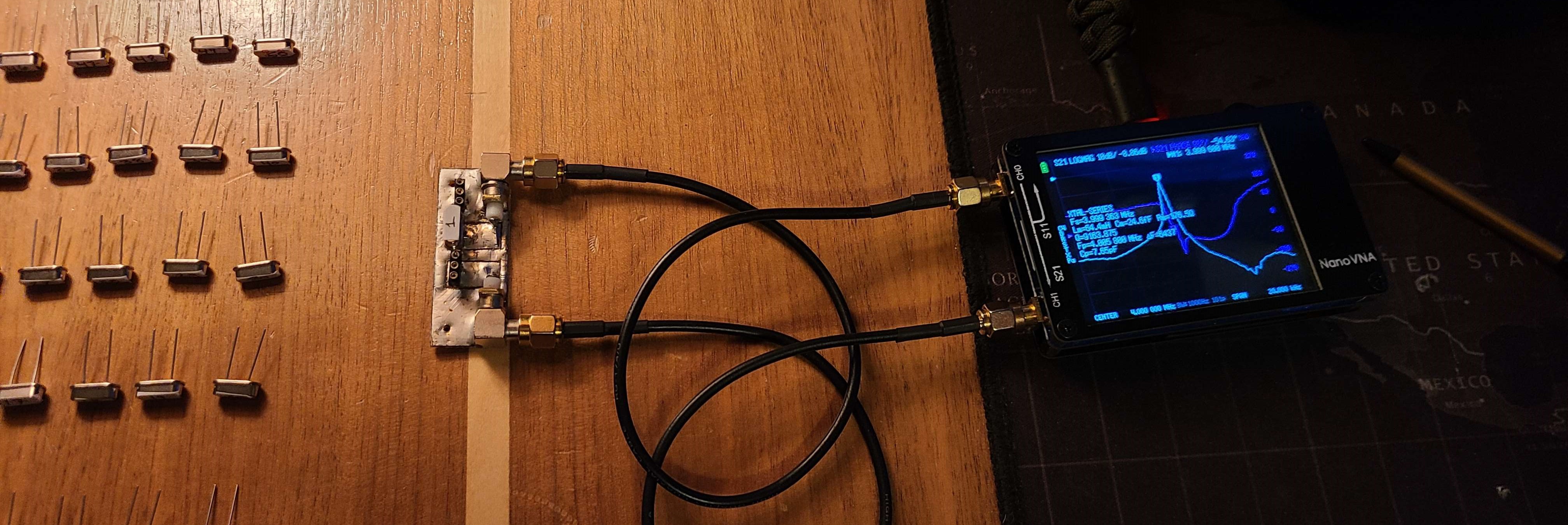
Settings: IF Bandwidth: 30 Hz, Center Freq.: 3.99400 MHz, Span: 3 kHz, Frequency Step: 30 Hz, 101 Points
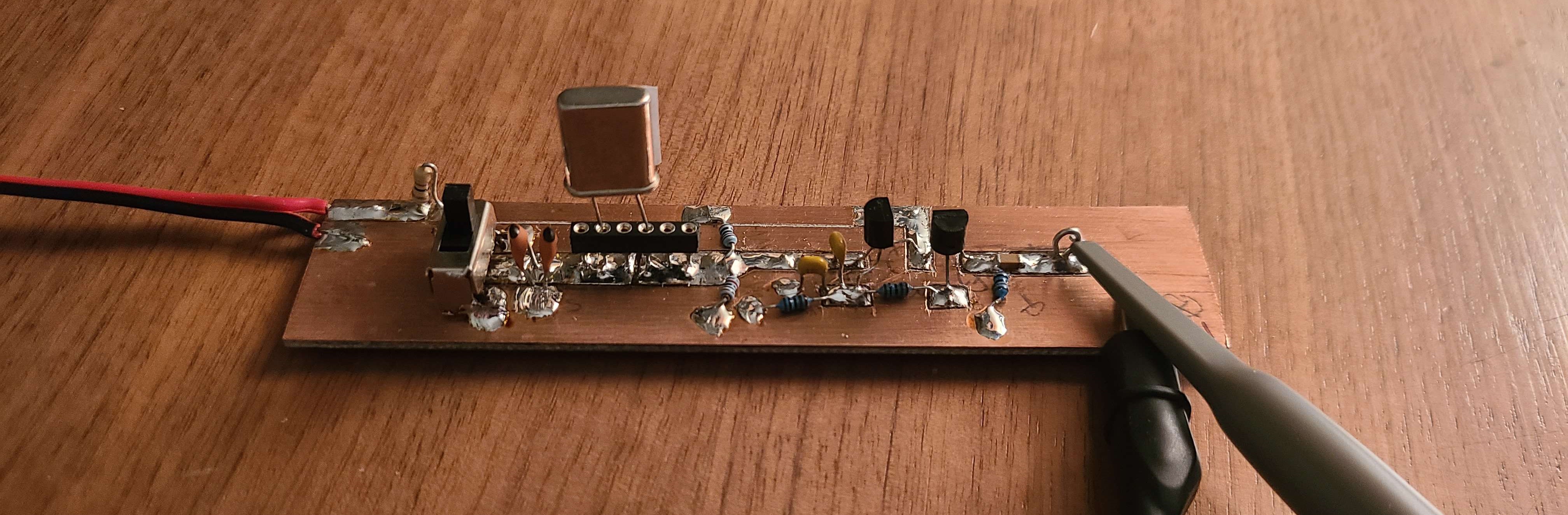
G3UUR Test Board
The G3UUR Method utilizes a Colpitts oscillator and a mount for the crystal with a switch to toggle a loading capacitance. By measuring the frequency difference caused by including the loading capacitance, the motional parameters of a crystal can be calculated. G4OEP has a good resource written on the derrivation of these equations here. This method produces results not far off from the NanoVNA results.
Construction
I began by finding all the parts I needed from my parts bins. I don't seem to have any reliable NP0 47 pF capacitors, so I used two 22 pF capacitors in parallel and hoped the stray capacitance of the fixture would fill in the rest.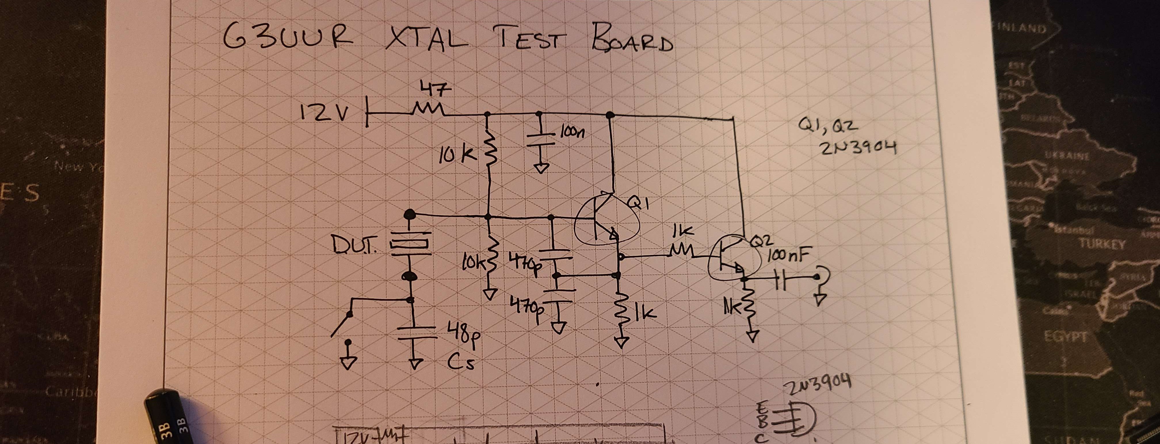
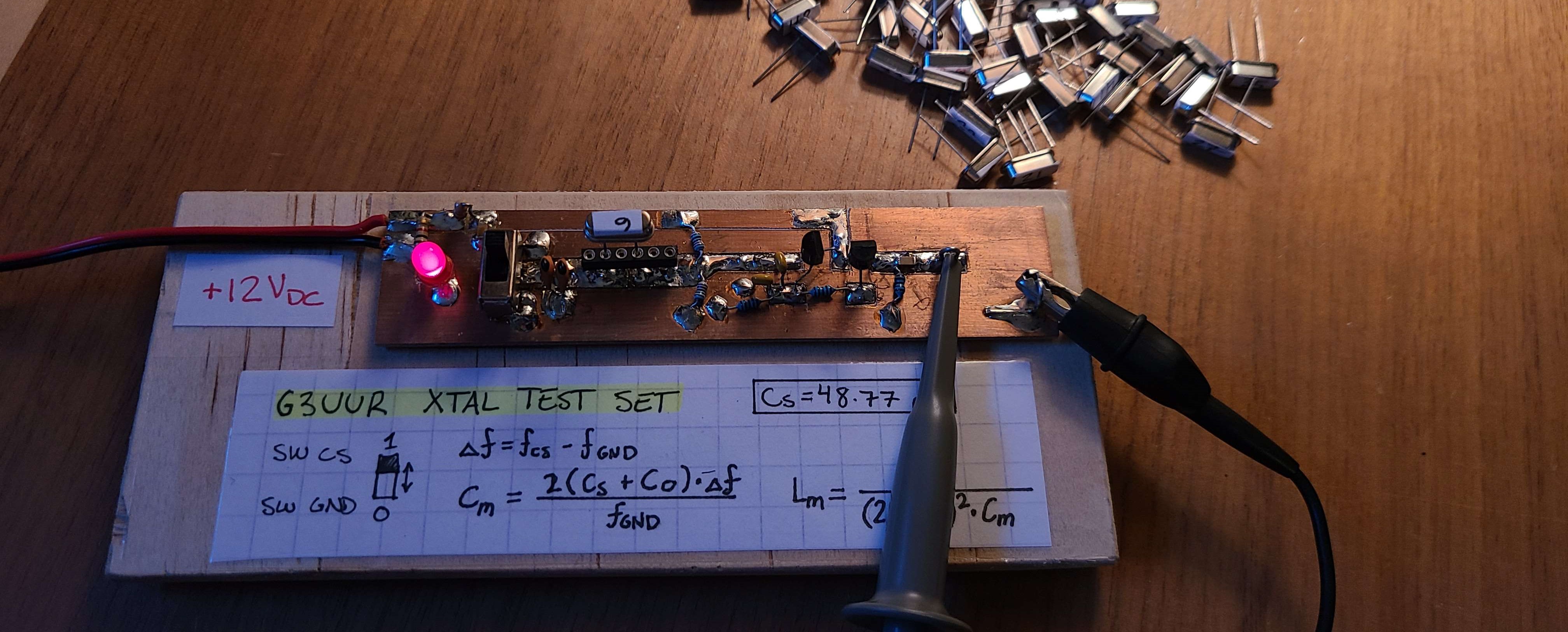
With the test circuit built, I mounted it to a small piece of wood and added the necessary equations for calculating the motional parameters. I also added an LED for indication that the circuit is being powered.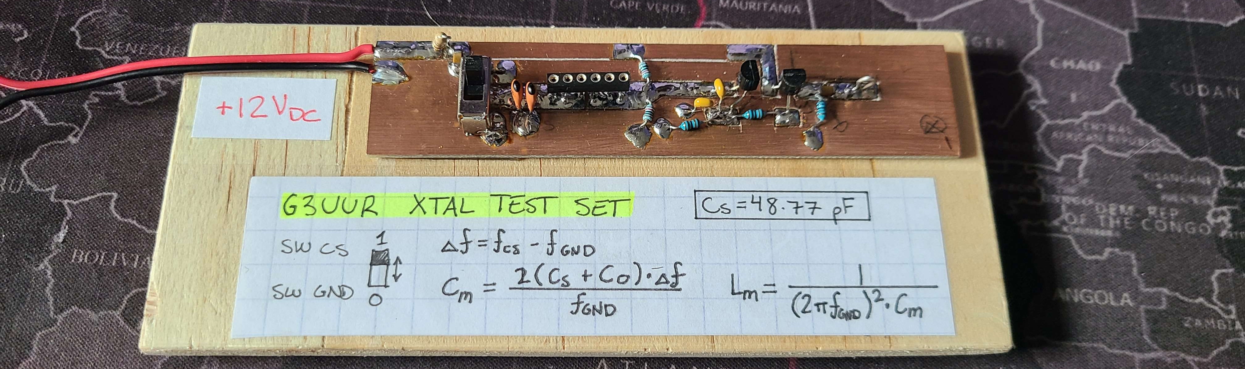
To measure the capacitance of the loading capacitor (and the stray capacitance of the pad it's soldered to) I used my LC-100A capacitance/inductance meter. I measured it out to be approximately 48.77 pF.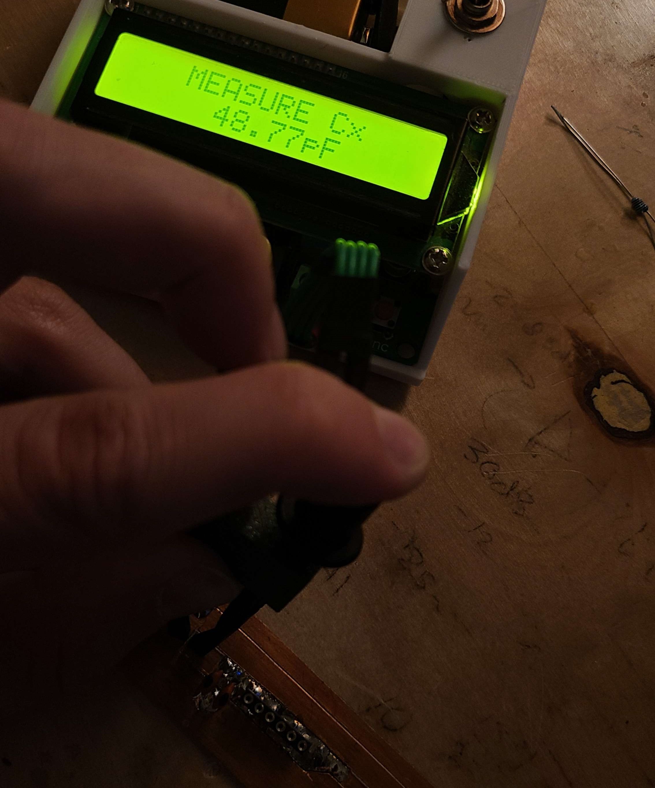
Measurement
Measuring all 50 crystals took a little bit of time. Using my Fluke 1900A frequency counter, I recorded all the frequencies in a spreadsheet and had the calculations print out the motional parameters Lm and Cm. The G3UUR method doesn't provide the motional resistance so that must be found another way. In my case all I cared about was the motional capacitance and inductance.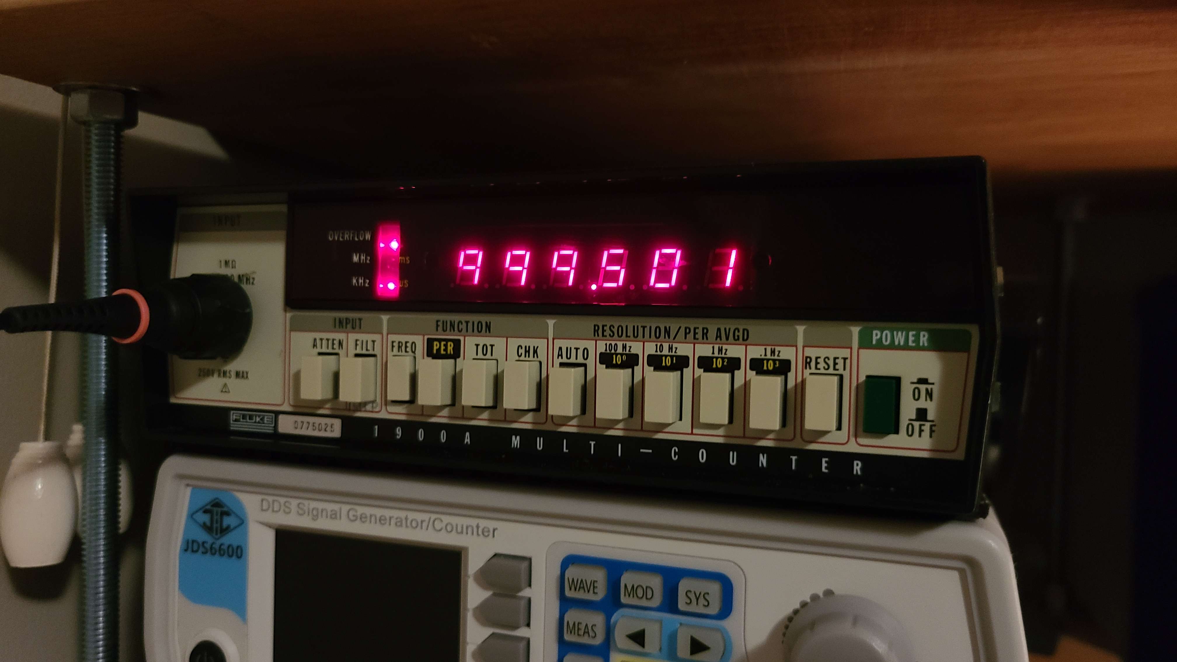
By allowing the Fluke 1900A to go into "overflow" I was able to get an accuracy of 1 Hz.
Results
Both the NanoVNA measurements and G3UUR methods measurements were taken and recorded in a spreadsheet. The G3UUR measurements were consistently around 8-10% off from the NanoVNA measurements.
The distribution of frequencies and motional inductances are plotted in the following histograms: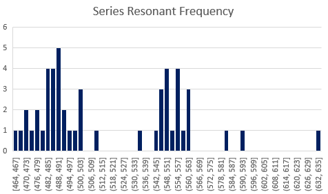
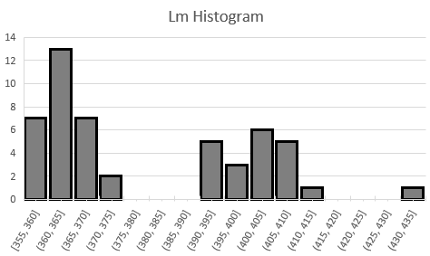
Most crystals had a series resonant frequency around 3.999489 MHz or so, and a motional inducatance around 362 mH.
The following spreadsheet shows the first 25 crystals, with the average values and errors being from the whole bin of 50.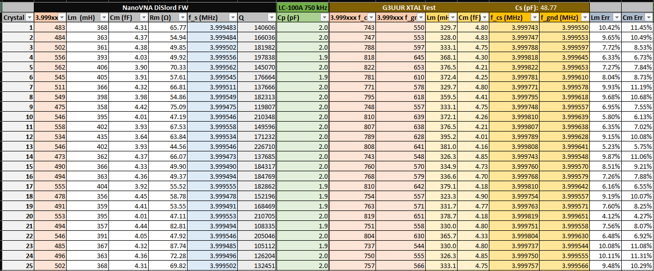

Remarks
I have learned a lot about the characterization of crystals in the past weeks, and with this knowledge I plan to design a better crystal filter. Quartz crystals have some very neat properties and applications outside of oscillators that I never knew about, so this sub-project has been quite educational and fun for me.