After a dissapointing first attempt, I redesigned the crystal filter again. This time using a slightly different approach.
I chose to look into how to properly design a crystal filter, and many sources pointed to the use of a software called Dishal by DJ6EV. Dishal Software The Dishal software is available for download from a number of sources such as changpuak.ch, minikits.com.au, bartelsos.de. Note: if you download using these links, I will take no responsibility for any problems or damages that may occur.
Crystals
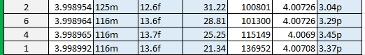
As covered in the first approach to the crystal filter, I characterized the crystals I have available to me. In the case of the filter built in this approach, I am also using the same set of 4.0000 MHz crystals. This time I chose the closest 4 crystals.
Design and Calculation
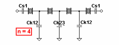
The design was made using the software called Dishal by DJ6EV. By inputting the crystal characteristics, number of crystals, desired bandwidth, and passband ripple, it will provide the necessary capacitor values to complete the crystal ladder.
Using the crystal characteristics, namely the motional inductance and holder capacitance, I designed a 3 kHz bandwidth chebychev filter (0.3 dB passband ripple).
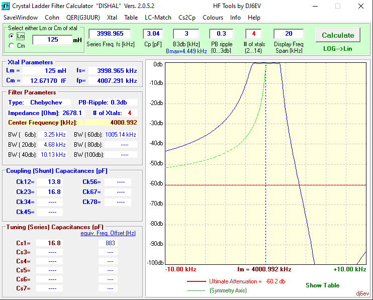
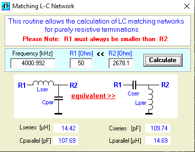
A lesson learned from the previous approach is that the impedance matching on the input and output of the filter is essential to achieving a good passband result. The nice part about the Dishal software is that it provides the input and output impedance of the filter and provides a built in matching network calculator.
Using this matching network calculator, I calculated the necessary inductance and capacitance values to match the 2680 ohm impedance to 50 ohms.
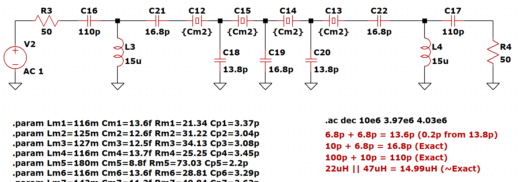
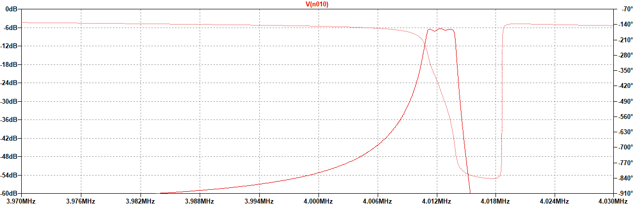
After calculating all the values I needed, I then constructed the schematic in LTspice and ran a frequency response simulation to see if the results vary from what the Dishal software was providing. Overall it turned out quite similar and had a clean passband with the correct bandwidth.
Passive Components
Being that I don't have any 15 uH inductors, 13.8 pF capacitors, or 16.8 pF capacitors, I had to mix and match components.
For the capacitors, I used two 6.8 pF capacitors in parallel to achieve a value of 13.6 pF, and a 10 pF in parallel with a 6.8 pF to achieve 16.8 pF.
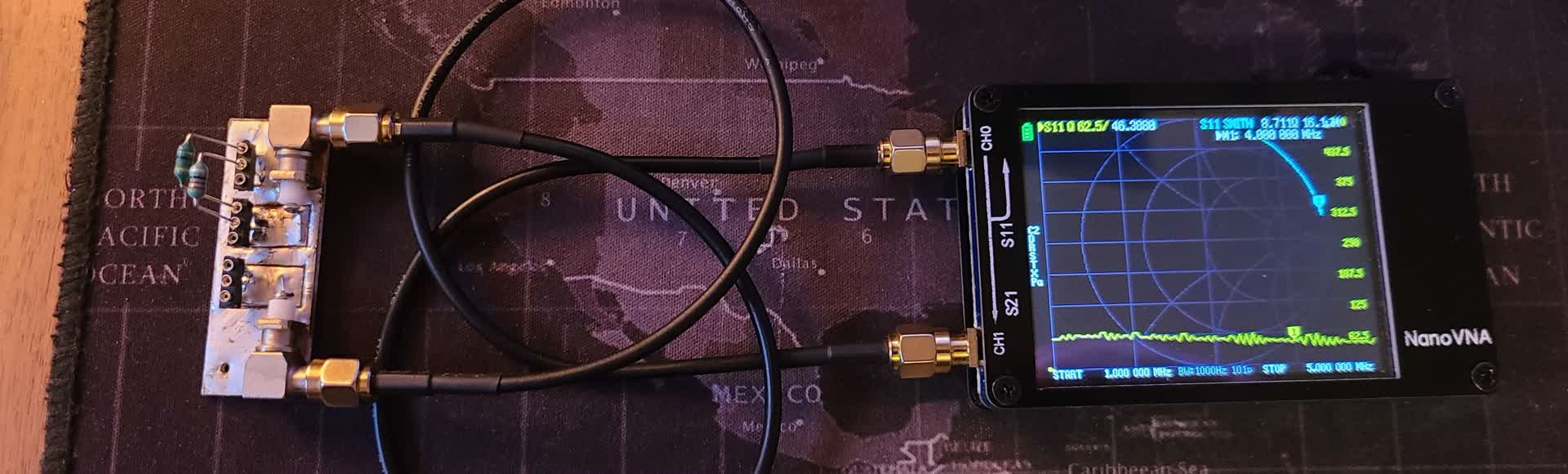
For the inductors, I used a 22 uH in parallel with a 47 uH, which achieved an ideal value of approximately 15 uH. Testing this on the NanoVNA I saw a Q factor of around 50 for the combination.
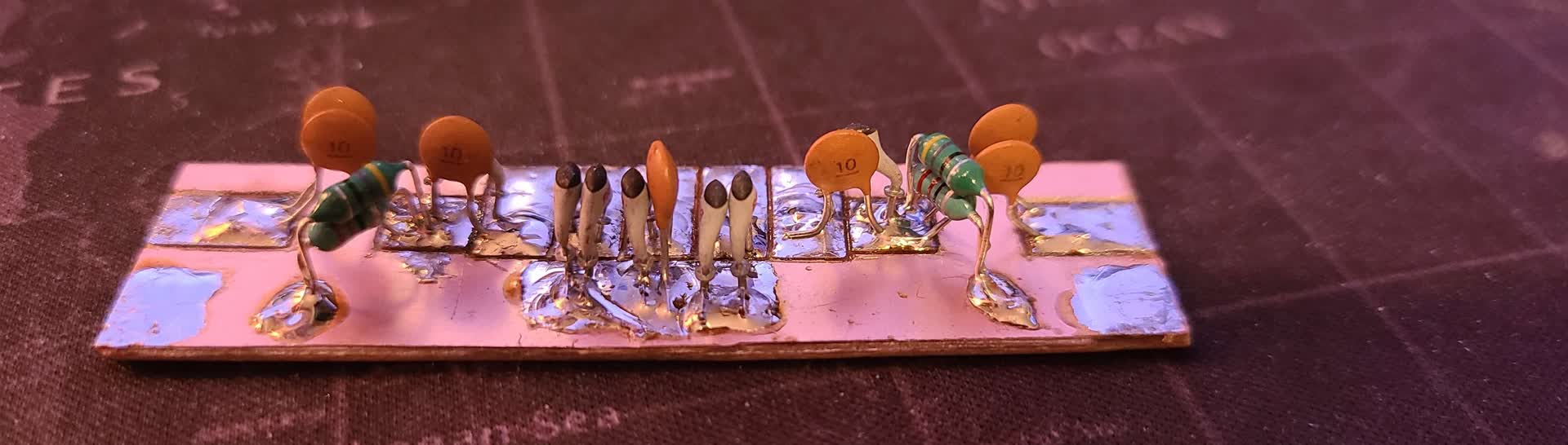
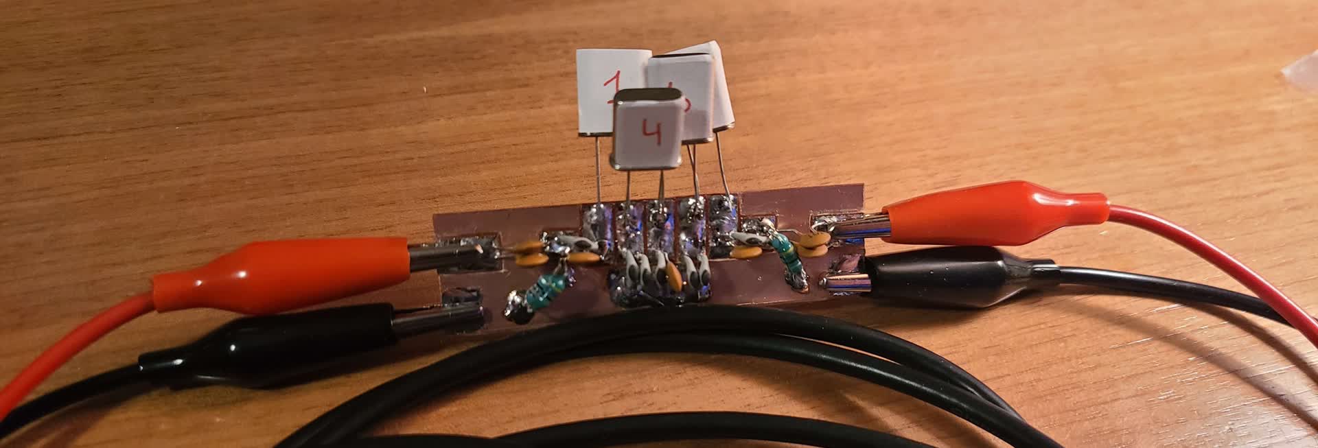
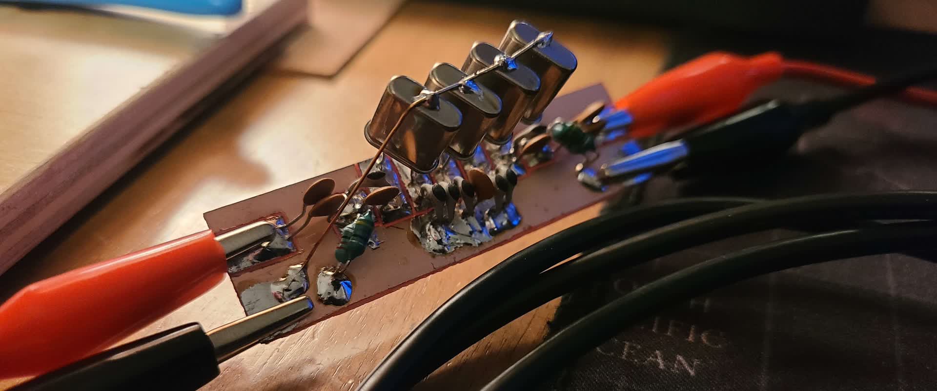
Filter Construction
The filter was built using the same piece of copper clad board that the previous crystal filter was built on. This time changing all the components for the ones I calculated.
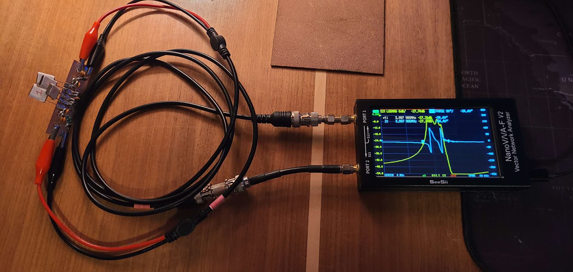
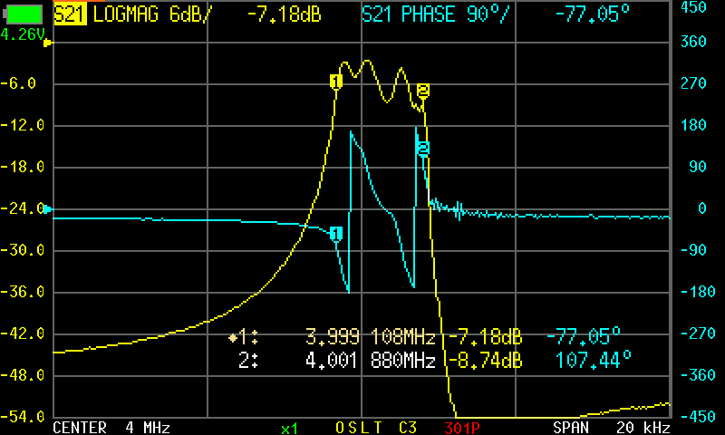
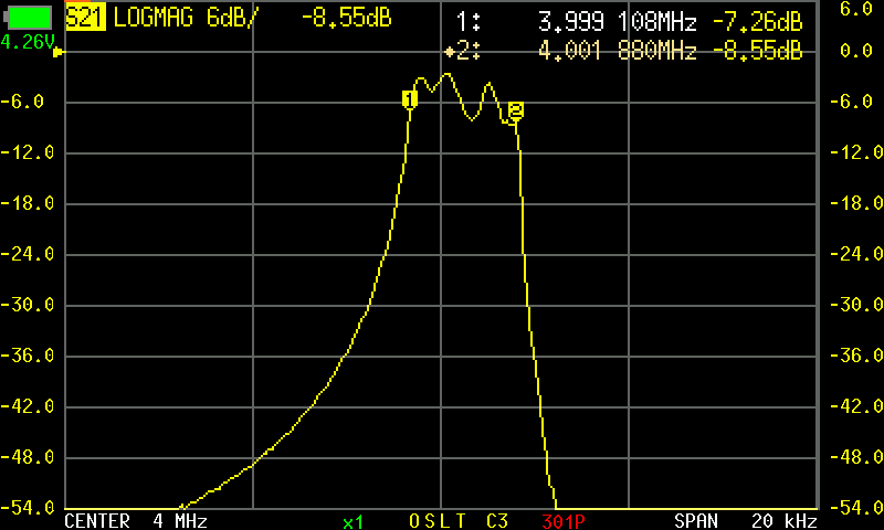
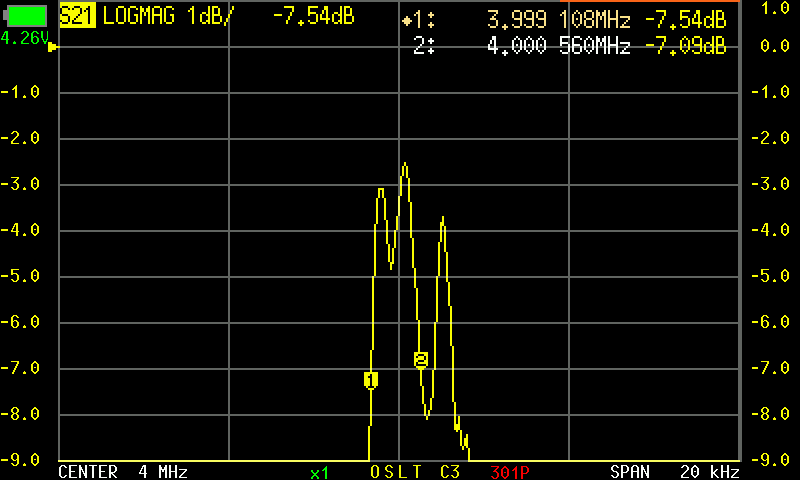
With the filter board built, I tested the filters response using the NanoVNA-F v2. This time the filters response was much more desirable, and looks similar to what was simulated, but with a lot more passband ripple. The bandwidth is as expected.
Remarks
I attribute the excess passband ripple to the makeshift nature of the board. I will be ordering new components soon, so I will make sure to include various inductor values to ensure I won't have to stack them in parallel like I did here. Additionally, to find some capacitors more closely valued to what is needed would help as well.
The mismatch in each crystals parameters may have also played a role in the lesser than desired response. For that reason I am also ordering a large batch of 4 MHz crystals to later sort through and characterize.