With the new crystals characterized, I take on a new approach to designing a crystal filter.
Crystal selection
Utilizing the spreadsheet I made of the charactarized AS-4.000-18 Crystals (4.000 MHz), I sorted through and produced 3 different sets of closely characterized crystals.
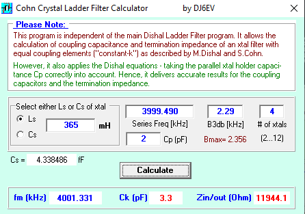
Crystal Set 1
Average Parameters: Fs = 3.999 490 MHz, Lm = 365 mH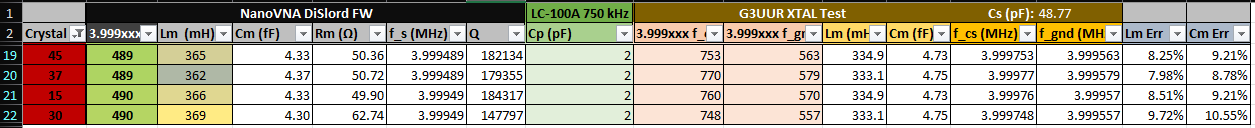
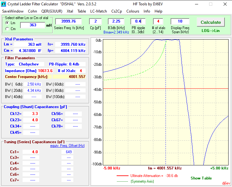
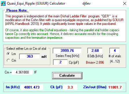
Crystal Set 2
Average Parameters: Fs = 3.999 760 MHz, Lm = 363 mH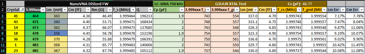
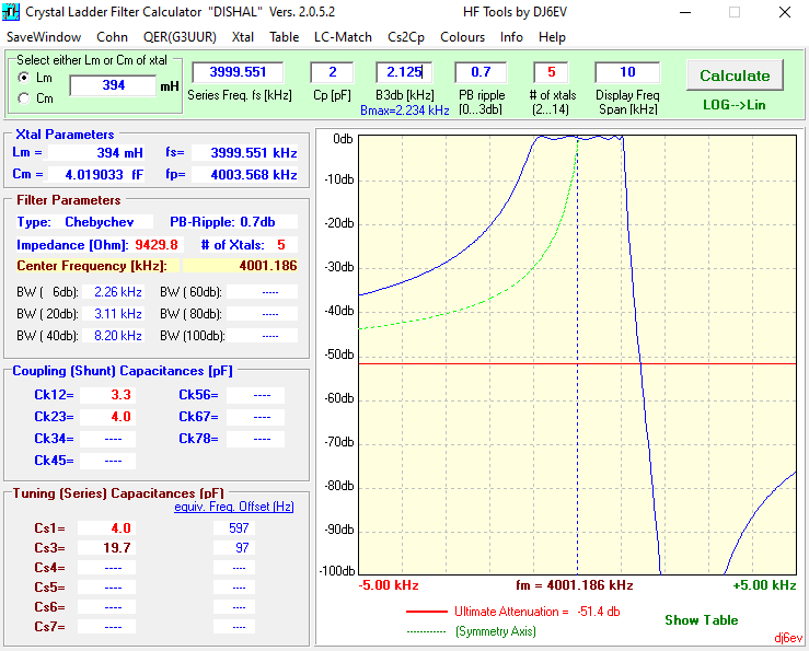
Crystal Set 3
Average Parameters: Fs = 3.999 551 MHz, Lm = 394 mH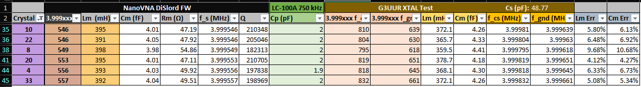
Calculating filter values
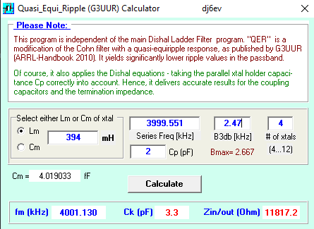
To make the filter calculations I used the software Dishal by DJ6EV (1). The Dishal software has mutliple filter types that can be designed, such as A butterworth, chebysheb ladder filter, a Cohn filter, or a Quasi-Equi-Ripple (QER) filter. I decided to run the calculations on all types to see what best fit my selection of crystals.
Software
The Dishal software is available for download from a number of places such as changpuak.ch, minikits.com.au, bartelsos.de.
Note: if you download using these links, I will take no responsibility for any problems or damages that may occur.
I adjusted the bandwidth to match the standard 3.3 pF capacitor value as I have plenty on hand. The target bandwidth is between 2.2 kHz and 3 kHz. Crystal Set 1 (expand to view) Chebyshev Filter Cohn Filter Crystal Set 2 (expand to view) Chebyshev Filter QER Filter Crystal Set 3 (expand to view) Chebyshev Filter QER Filter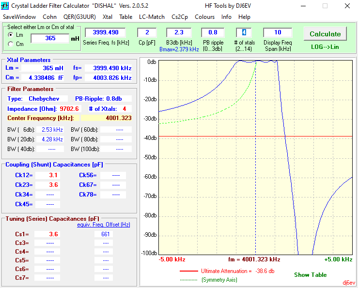
Selected Filter
I selected Set 2 of crystals in the QER configuration.
To match the impedance I utilized Dishal's built in LC match tool to calculate the needed values.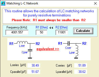
Building & testing the filter
NanoVNA-H (v1) and NanoVNA-F (v2) Differences to be aware of...
The NanoVNA-H (v1 by edy555) and the NanoVNA-F (v2 by Sysjoint) operate differently from eachother, and it is important to take note on how they sweep frequency.
When testing High-Q filters and components such as a crystal filter, sharp transistions can cause ringing in the time-domain response of the filter. In a measurement scenario where the filter is ringing, the measurement may end up being affected. Such is the case with the NanoVNA-F V2.
I connected both the NanoVNA-H (v1) and NanoVNA-F (v2) to my Rigol Oscilloscope and had the VNA's sweep from 1 MHz to 10 MHz. Looking at the output waveform on the scope, we can see the NanoVNA-F (v2) has discontinuities in its sweep as the oscillator is turning off after each sweep, and the NanoVNA-H (v1) has its oscillator constantly on.
NanoVNA-H (v1) Output Waveform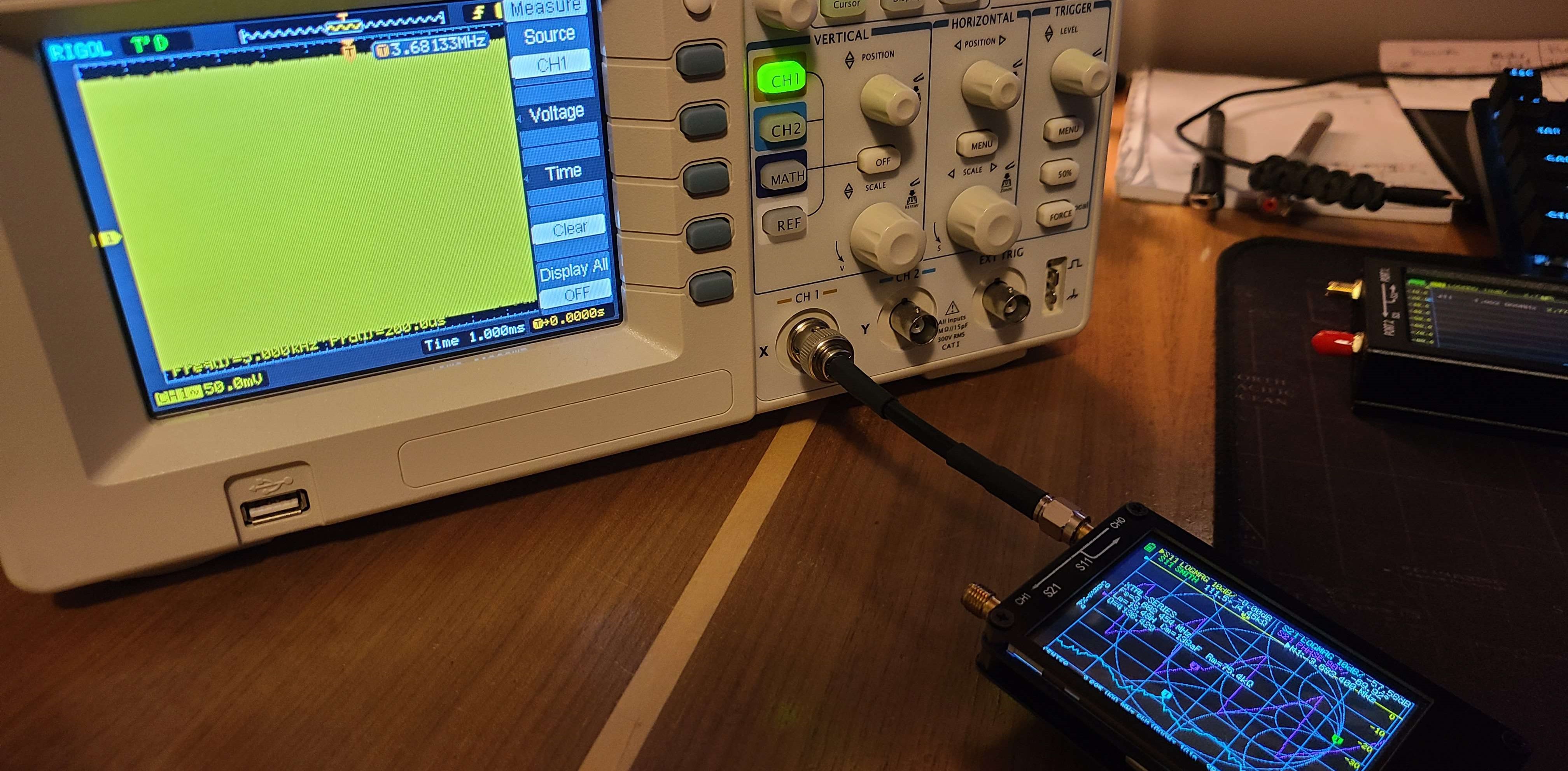
NanoVNA-F (v2) Output Waveform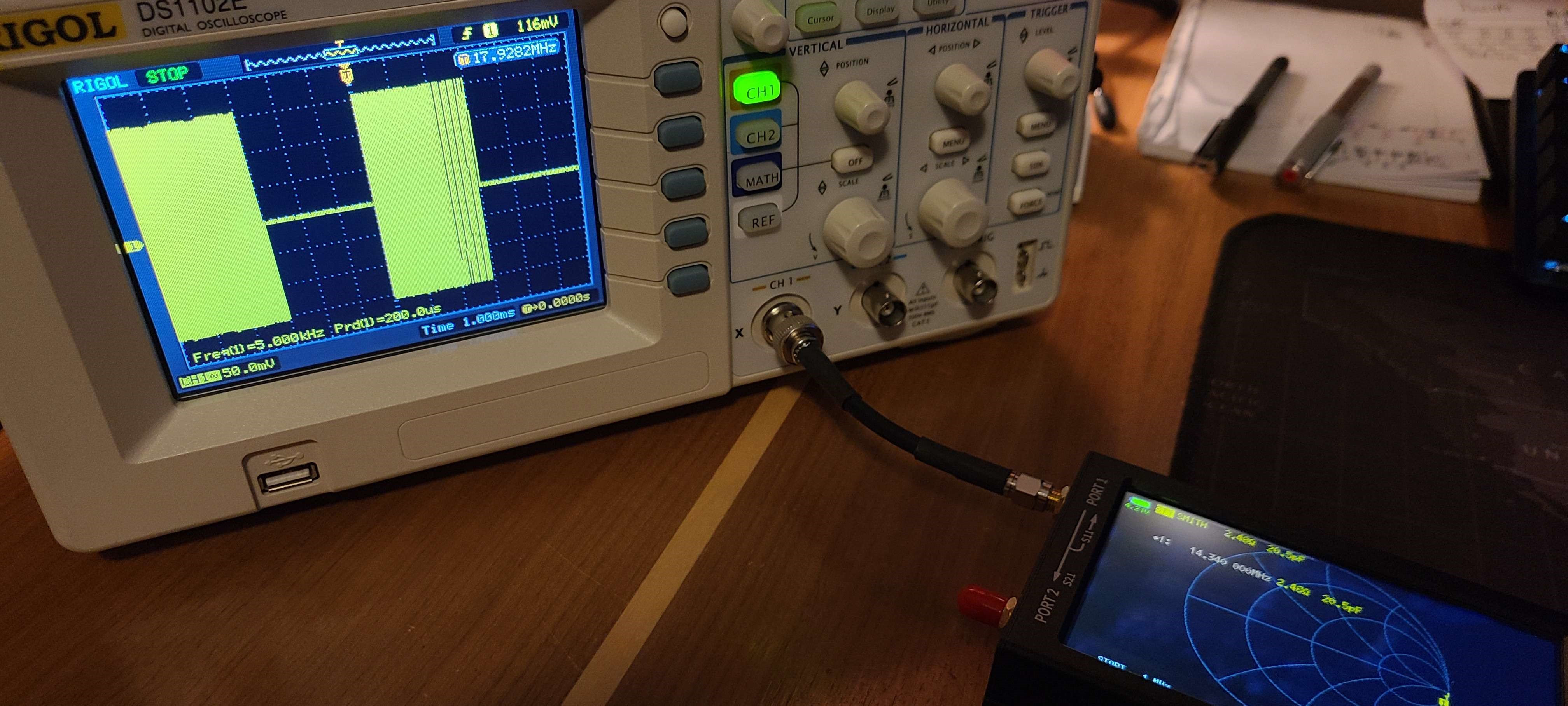
For testing High-Q components and filters, ^^the NanoVNA-H or NanoVNA-H4 is better^^. I recommend purchasing the NanoVNA-H4 as it can go up to 401 points using the DiSlord Firmware, and it has a 4 inch IPS display.
Testing the old filter (from approach 2)
Because of the new knowledge of the NanoVNA-H and NanoVNA-F's differences, I re-tested the filter from approach 2 to make sure the poor response wasn't from the NanoVNA-F v2.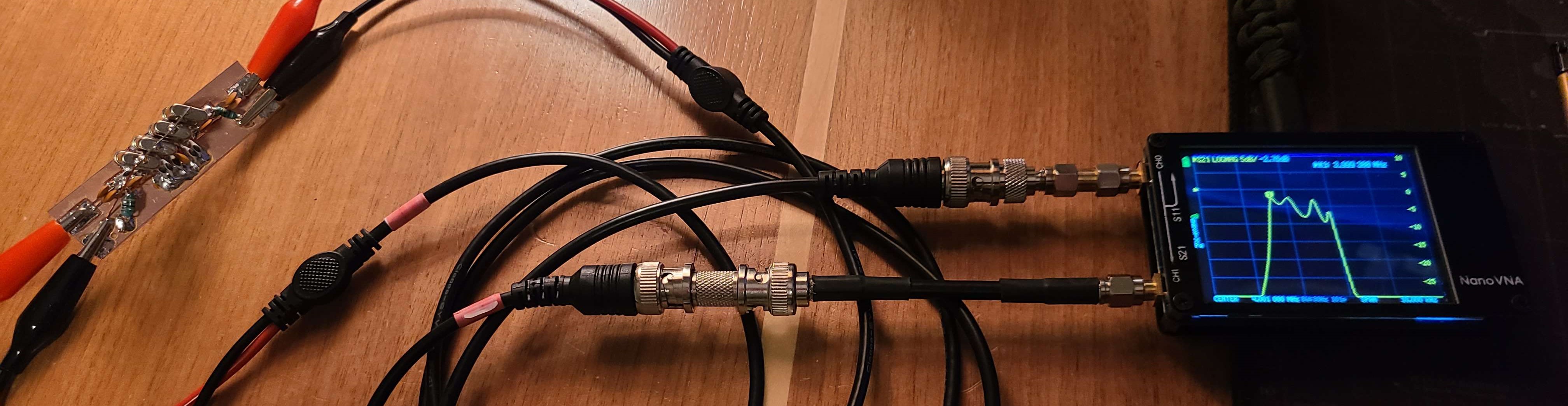
The response ended up being similarily just as bad.
Testing the new filter
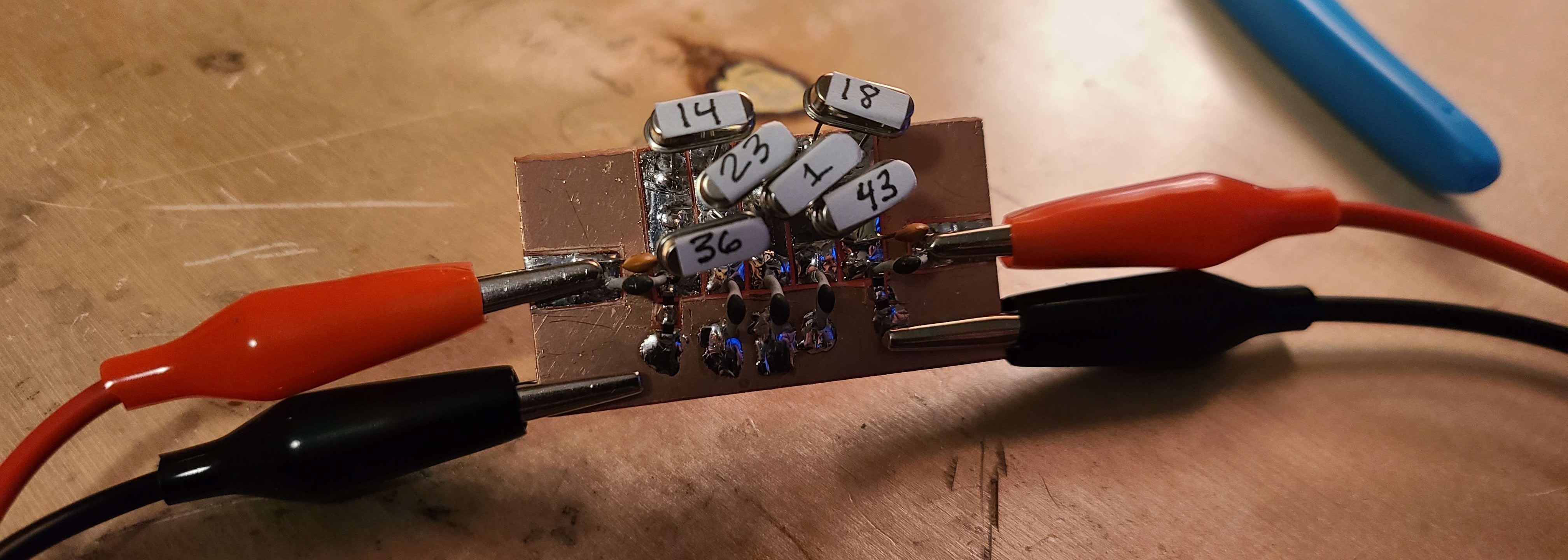
The filter was built once again on a cheap piece of one-sided bakelite copper clad board. I initially built the filter with some trimmer capacitors on the input and output matching network to find the best response from the filter. After which I desoldered the caps, measured them, and found the corresponding values in my parts bins.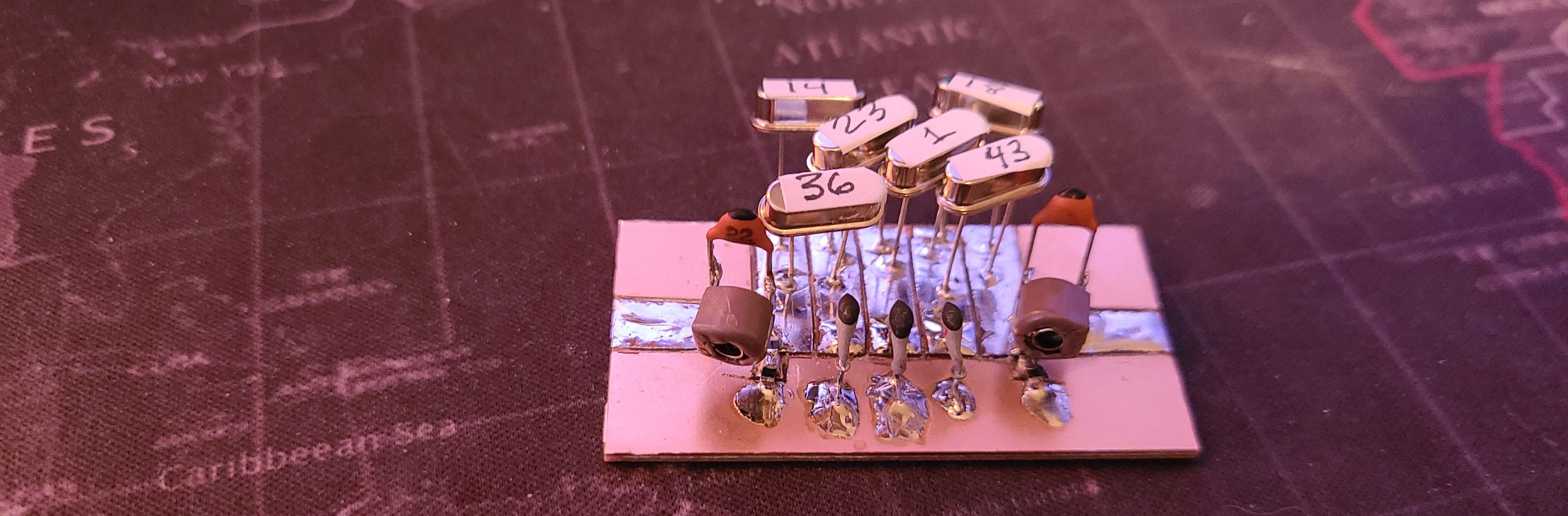
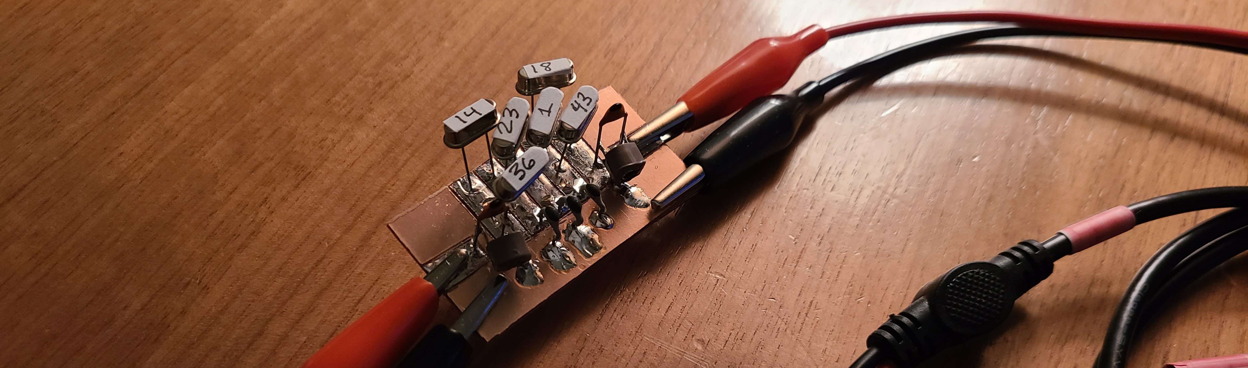
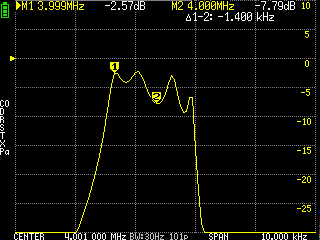
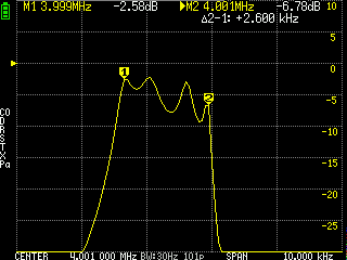
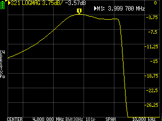
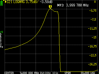
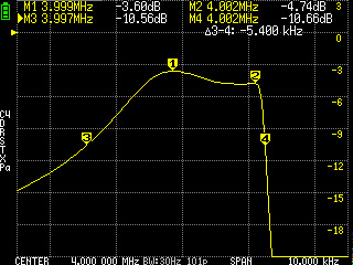
I tested the filter and adjusted the trimmer capacitors until I was happy with the response. I later settled on a fairly wideband response with a shallower roll-off on the low end. This was not ideal, and I would much prefer a steeper roll-off but for now this will do, as it is my first filter.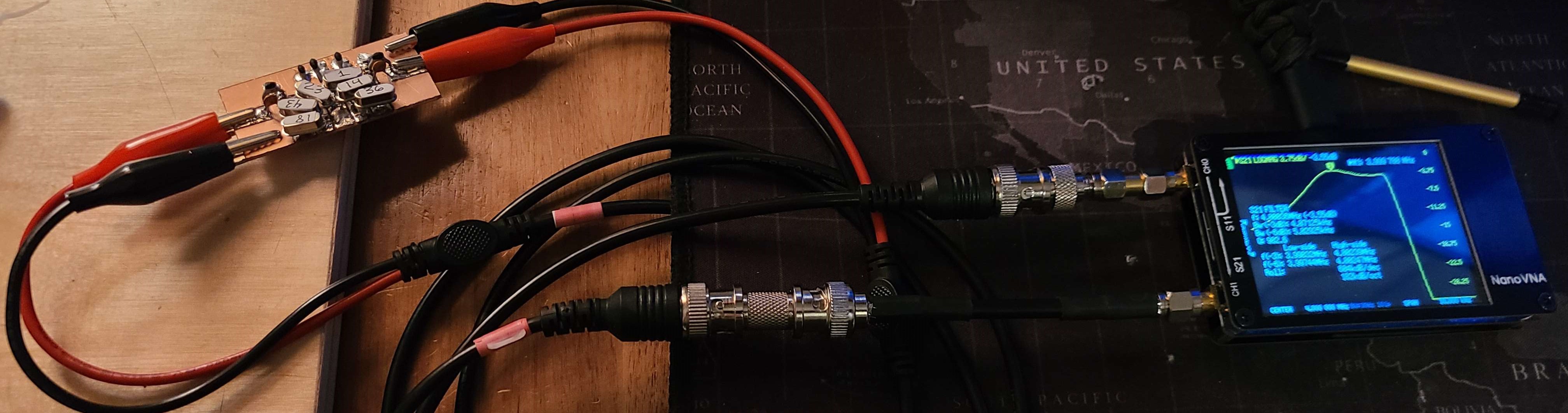
The response I settled on was fairly flat.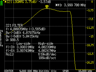
Challenges and Remarks
In either to get the desired bandwidth of between 2.2 kHz and 3.0 kHz with the 4 MHz crystals, very small shunt capacitances were used in the ladder. Not only are these small and subject to variation, but the variation can cause large changes in the response resulting in a less than ideal instability.
From what I have learned, typically you need higher frequency crystals for wider bandwidths, with SSB crystal fitler frequencies being between 6 MHz and 10 MHz.
The 4 MHz crystals would work much better for narrower bandwidths such as 400 Hz to 700 Hz CW crystal filters.
Most homebrew and commercial SSB crystal filters use 9 MHz crystals.
In future crystal filter designs I will try various frequencies to see what works best.