Still unsatisfied with my crystal filter, I decided to order some 8 MHz crystals. This decision ended up producing the best crystal filter for the reciever.
Crystal Filter Design
Crystal Selection & Characterization
When my previous crystal filter prototypes kept giving me unexpected and unimpressive results, I started reading some more on what could be the cause. I was able to pinpoint two major reasons:
- Crystal Frequency
- When I was using 4 MHz crystals, I was unable to get a good bandwidth given their characteristics. To achieve a bandwidth above 2.2 kHz using the 4 MHz crystals required I use very small series and shunt capacitors. This also meant that any stray capacitance of the pads on the PCB would have a larger effect on the filters response.
- Impedance Matching
- The filters response was heavily effected by any loading from an unmached load. Having a properly matched filter is important.
Because of the issues I was having with the 4 MHz crystals, I chose to use a different crystal frequency (which means a different intermediate frequency). A common frequency for SSB transcievers is 9 MHz, but after checking digikey, that frequency isn't a very common crystal frequency. With that, I decided to take a chance and buy some 8 MHz crystals instead.
I used my NanoVNA-H with DiSlord firmware (v1.2.40) to characterize the crystals. Using a frequency step of 30 Hz and IF bandwidth of 100 Hz, the following results were achieved.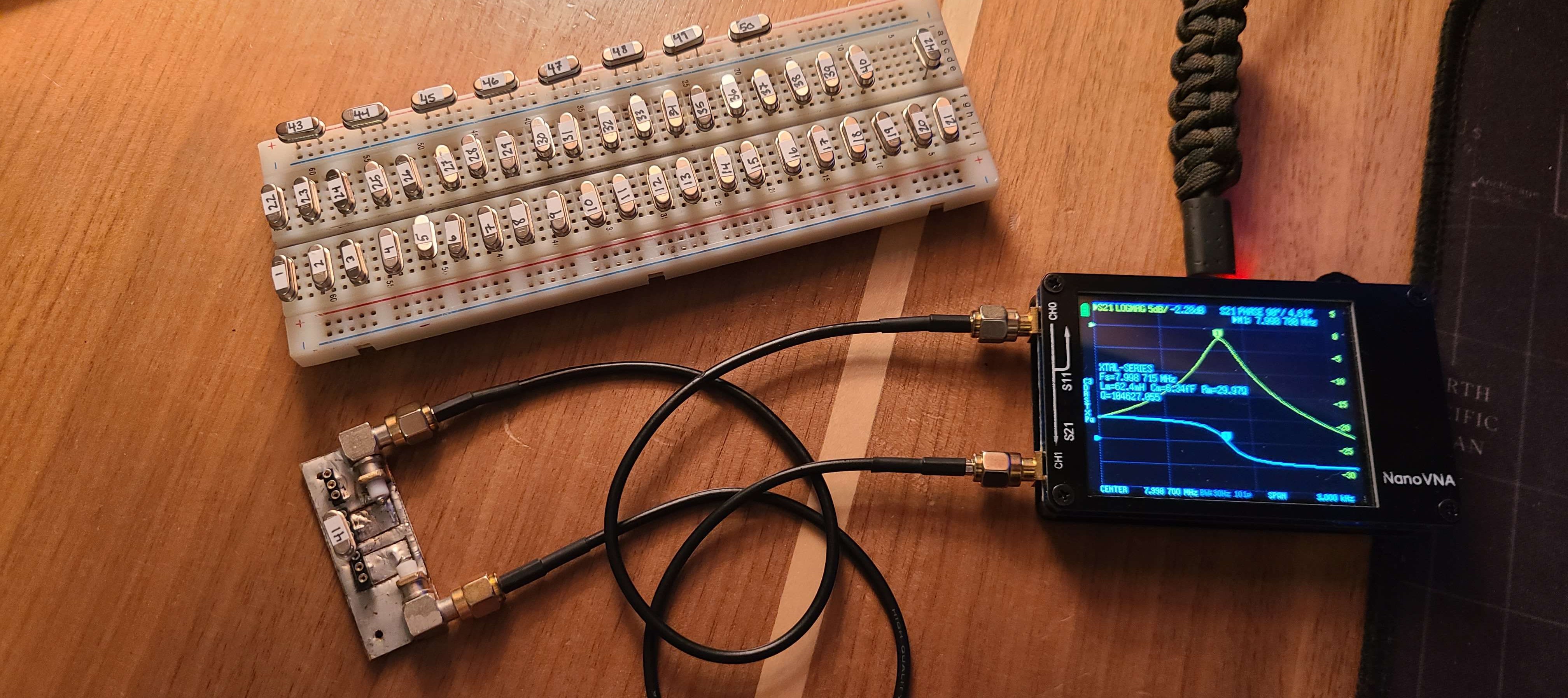
Screenshots of the NanoVNA measurements in gif format:
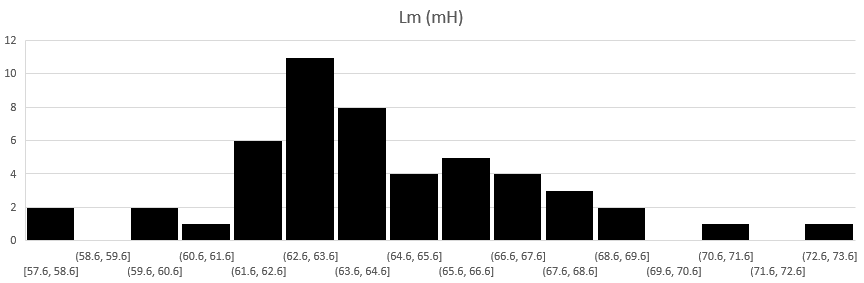
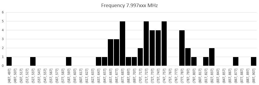
The distribution of the motional capacitance, inductance, and series frequency is shown in the following histograms.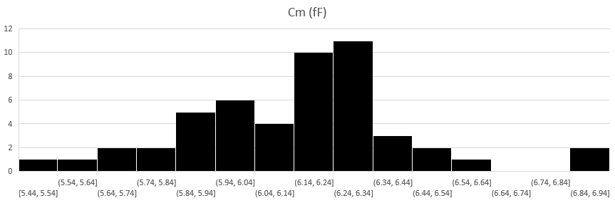
Calculating filter values
Once again, the filter calculations were done through the software Dishal by DJ6EV. Using the main program, I designed a chebyshev crystal ladder filter.
Software
The Dishal software is available for download from a number of places such as changpuak.ch, minikits.com.au, bartelsos.de.
Note: if you download using these links, I will take no responsibility for any problems or damages that may occur.
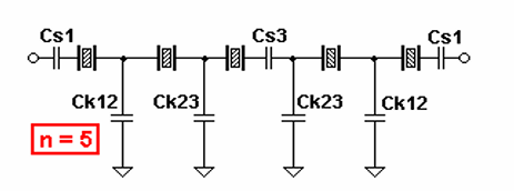
The filter used 5 crystals which share very similar motional parameters and frequency.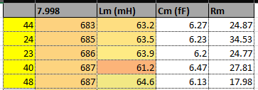
Using the characteristics of that set of crystals and parameters I set, the filters values were calculated.
The results from the calculations ended up being a Chebyshev fitler, with 0.08 dB of passband ripple. Impedance of 1246 ohms, and 3dB bandwidth of 2.8 kHz. The center frequency is 553 Hz above 8 MHz, which means the lower 3dB point is located at 7.999153 MHz.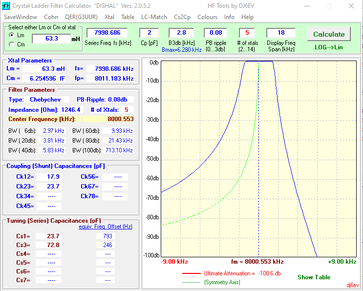
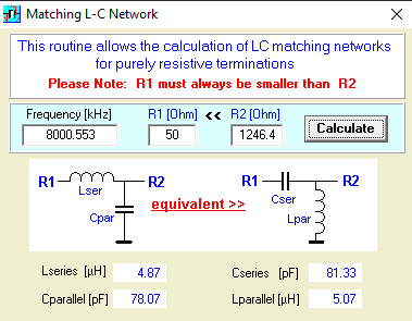
The capacitor values provided were larger and much more manageable than in previous designs. With the filter values calculated, the next step is to build the filter.
Building the filter
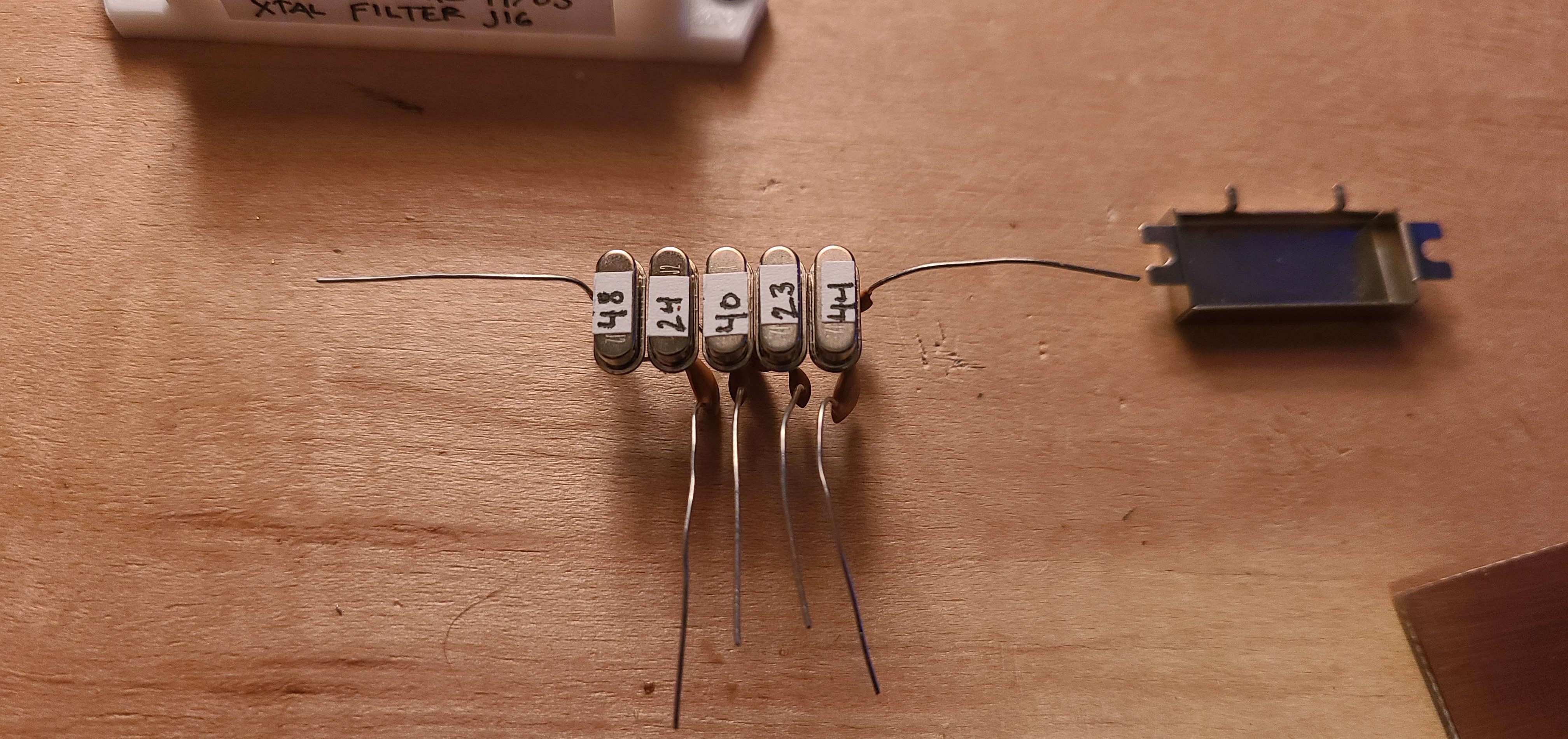
The filter was built using a different method this time. I took inspiration from a pre-made filter I saw built within a metal shield. I decided to make the filter free-form to some extent, so I needed to design a jig to hold the crystals in place while I free-form soldered.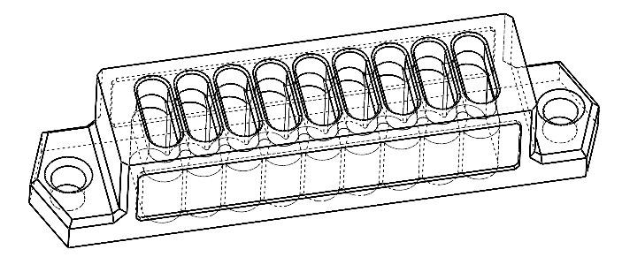
After 3D printing, I screwed it down to the plank of wood I use to cut copper clad board on. Using the jig I began soldering the filter together.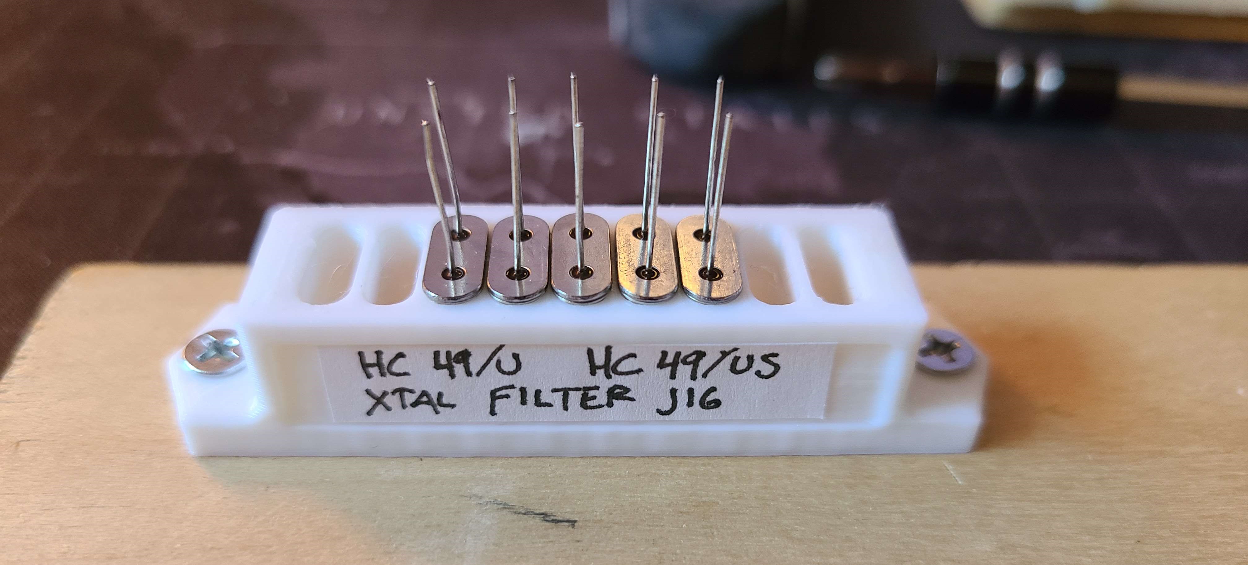
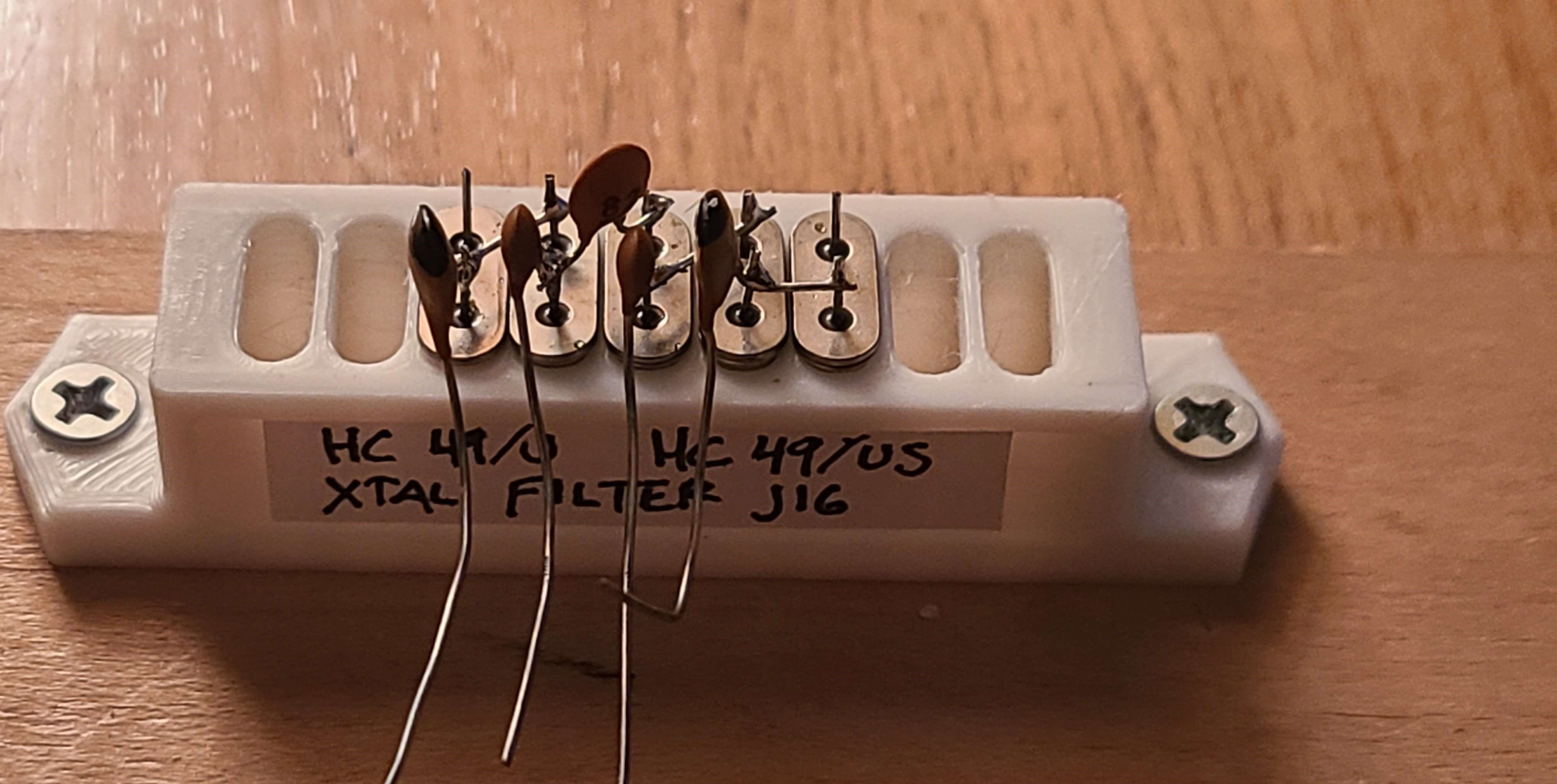
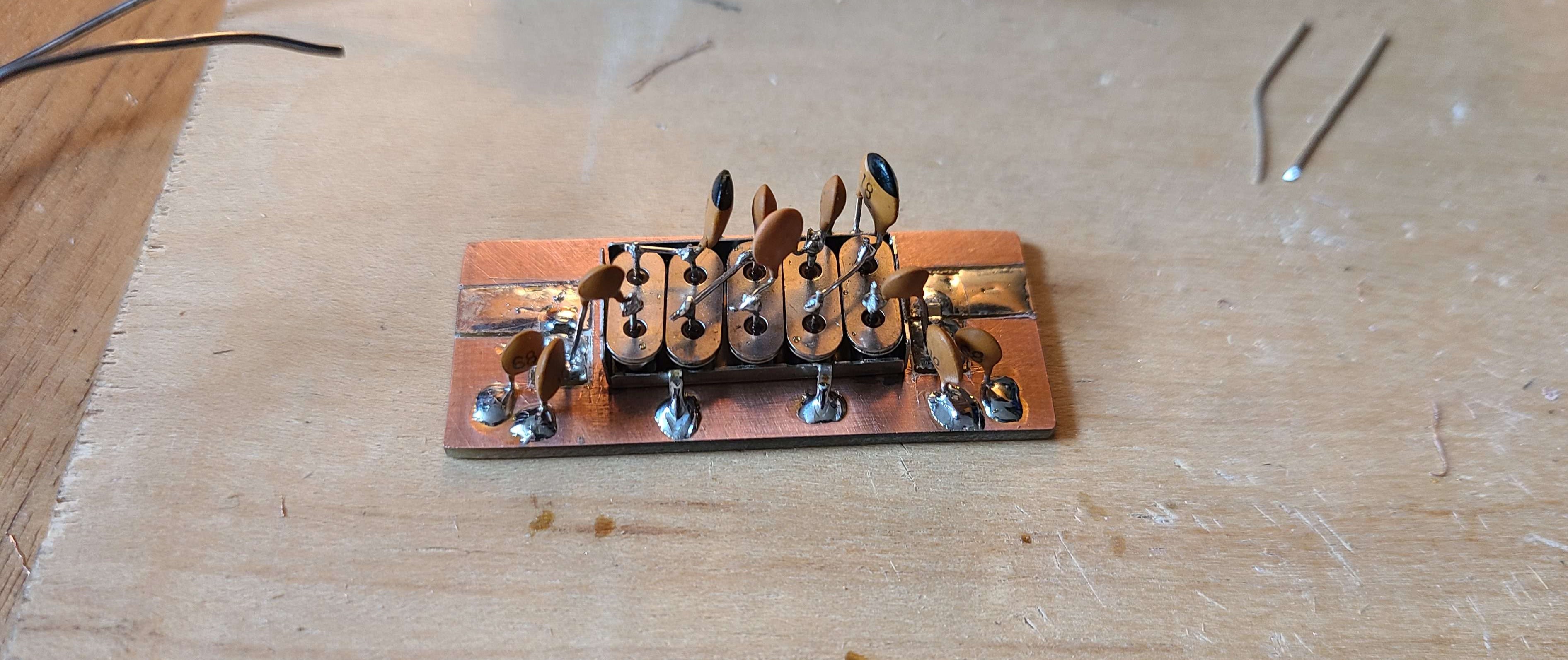
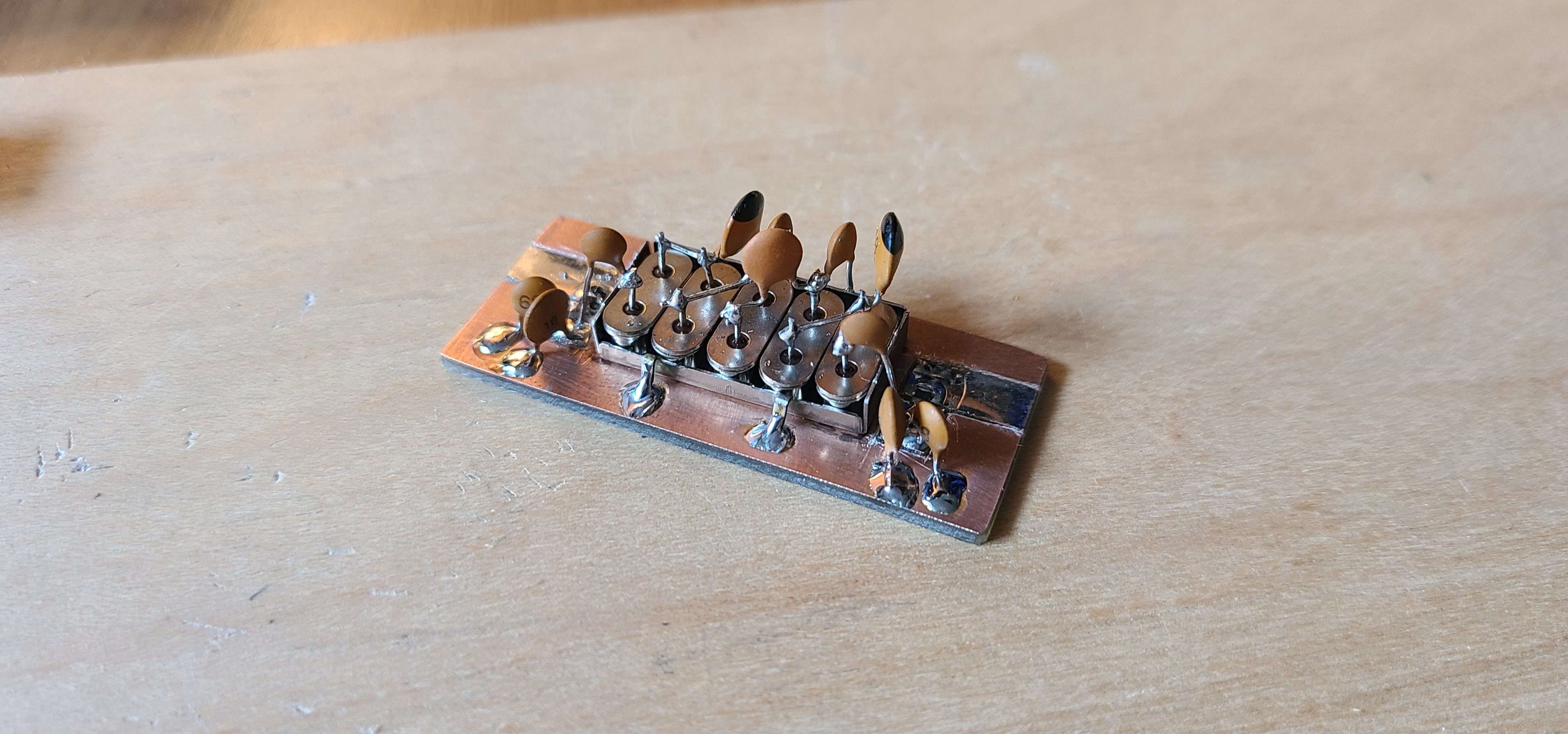
The complete crystal filter turned out well.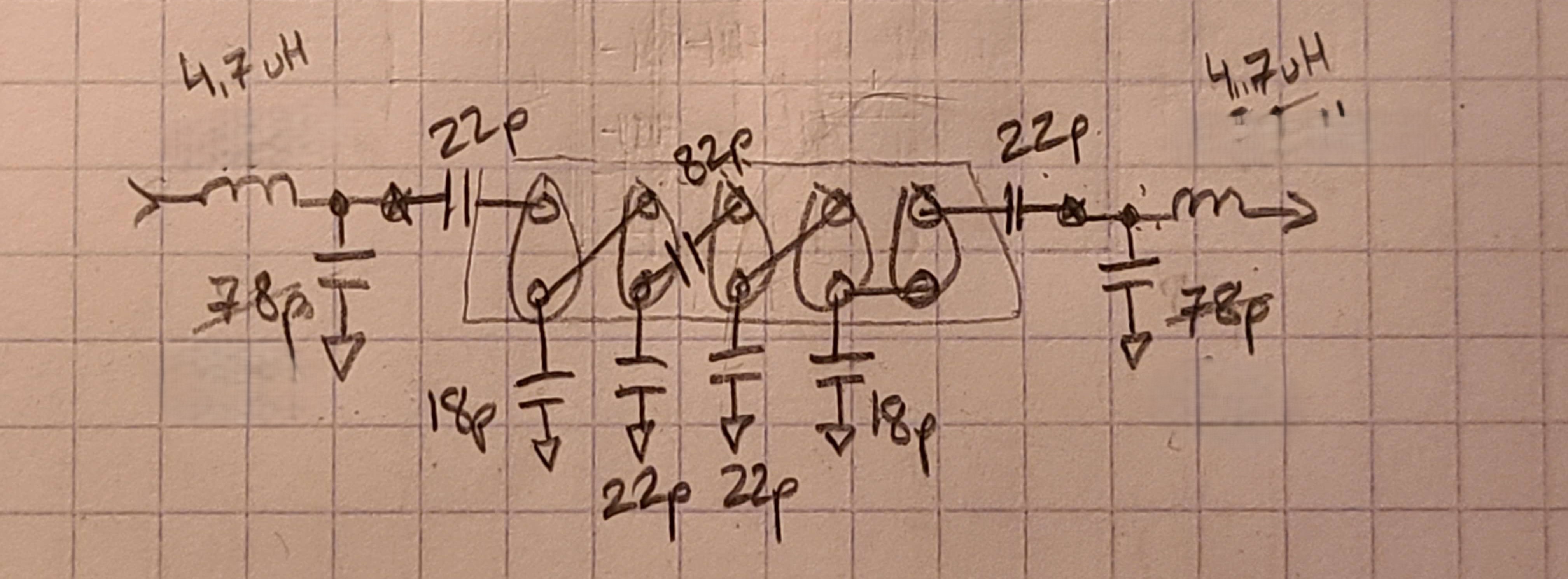
Testing the filter
The filter was soldered to a piece of FR-4 copper clad. The input and output matching networks were made with 0805 SMD 4.7 uH inductors, and a 10 pF capacitor in parallel with a 68 pF capacitor to make 78 pF.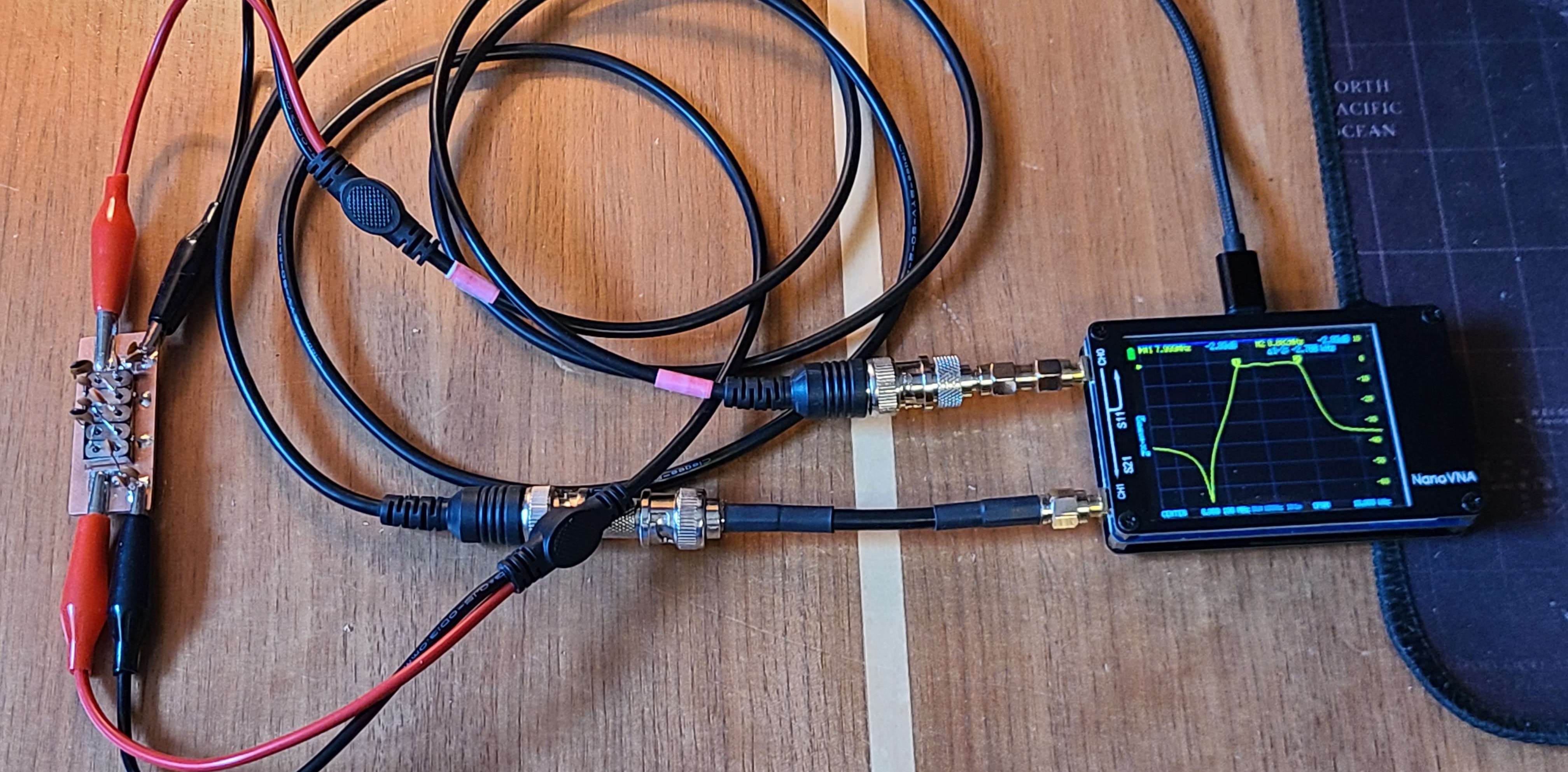
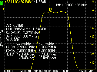
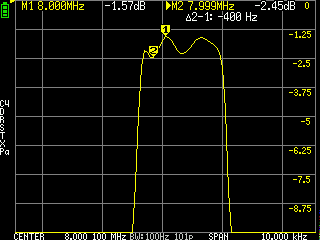
The resulting passband response is almost identical to the calculated response. The only noticeable issue was the 0.88 dB passband ripple, which is more than the calculated ripple of 0.08 dB. Other than the ripple, this filter has sharp skirts, and a 2.88 kHz 3dB bandwidth.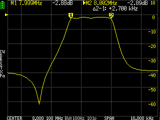
Remarks
I will call this crystal filter a success (among the other three attempts). With the crystal filter complete, all that is left in the superheterodyne reciever project is to make the IF filters, audio filters, and oscillators.
I have been thinking of re-designing the frontend RF amplifier as well, to decrease the gain and add an adjustable gain. I may design some automatic gain control into the IF amplifier as well.