The next step in building my 20m superheterodyne reciever is the crystal filter. This filter will determine the selectivity of my radio's tuning and dynamic range. The goal is to make a crystal filter with a bandwidth of 3 kHz for SSB operation.
The reason a crystal filter is used is because of the crystals high Q-factor and consistency. The topology I build in this approach is a 4th order Cohn filter.
Characterizing Crystals
The key component of a crystal filter are the crystals themselves. To properly design a crystal filter, the first step is making sure the crystals you use are very close in characteristics.
To characterize a crystal, there are four variables needed, three of which are known as the ^^motional parameters^^ of the crystal, and the last is the capacitance of the metal can that contains the crystal itself.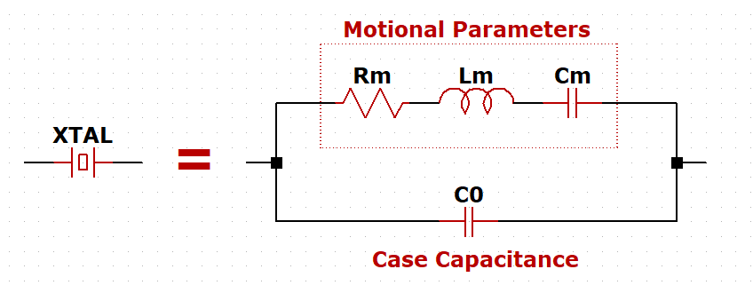
The motional parameters Lm and Cm determine the series resonant peak, and the parallel (shunt) capacitance C0 will determine the parallel resonant peak (anti-resonant peak). The Rm parameter is what limits the Q-factor of the crystal. Most crystals however will have a Q-factor above 1000, and in the case of a filter, we want a crystal with a Q-factor above 25000.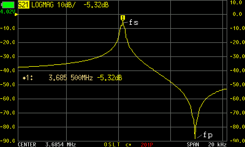
To measure these parameters, I used my NanoVNA-H with DiSlord firmware (v1.2.40). This firmware provides extra options for measuring crystal parameters directly.
Test Fixture
Before measuring the crystals I wanted to make a proper fixture to reduce any errors caused by wires, cables, or alligator clips.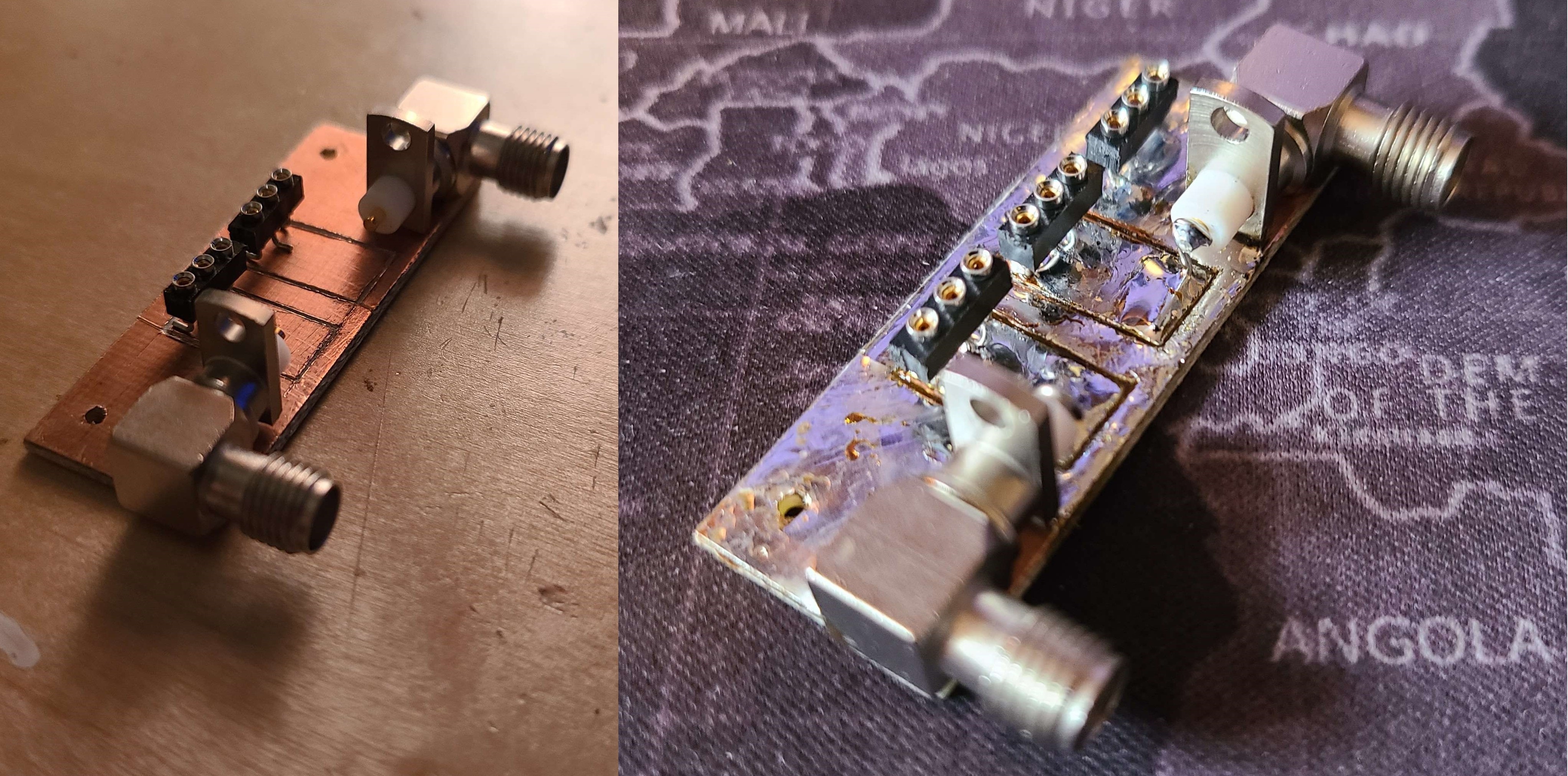

3.6864 MHz Crystals
I started by looking in my bin of miscellanious crystal oscillators and found 19 crystals set for 3.6864 MHz. Once I had my NanoVNA set up with my test fixture and going through my SOLT calibration, I started testing the crystals and recorded the following.
The batch of 3.6864 MHz crystals varied quite a lot, with a good number of low-Q and high-Q crystals mixed in. Recording the data in a spreadsheet, I sorted through which ones would be optimal for a filter.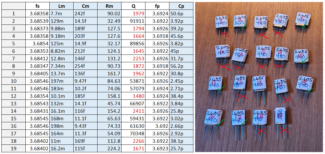
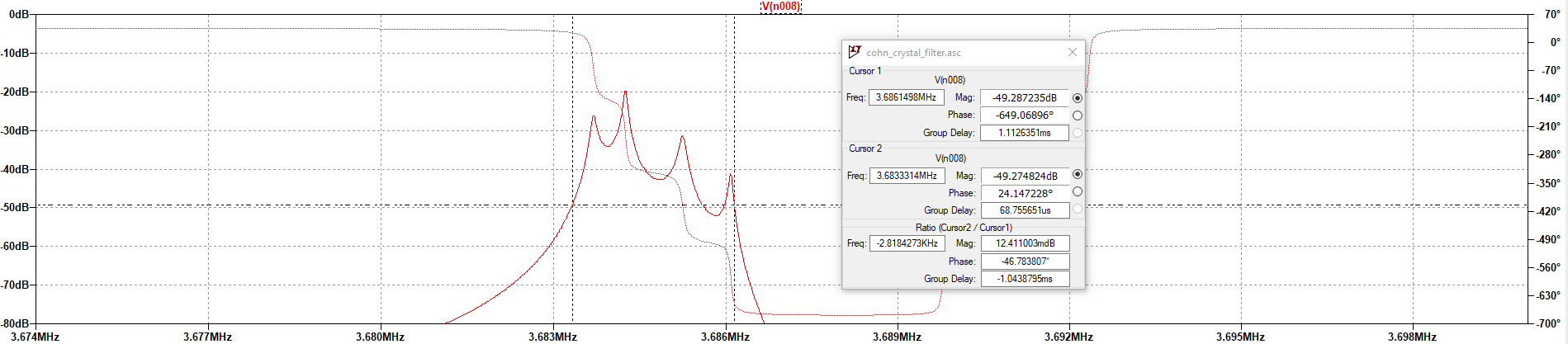
I then imported the crystal values into LTSpice and simulated the crystal filter structure I was aiming to make. Using two transformers to impedance match, and the parameters gathered from the NanoVNA, the simulation results were fairly underwhelming. Very high passband ripple, which is of course not ideal. -- Later on in this post I will cover what is going on here, but I will say it has to do with the input and output impedance of this filter.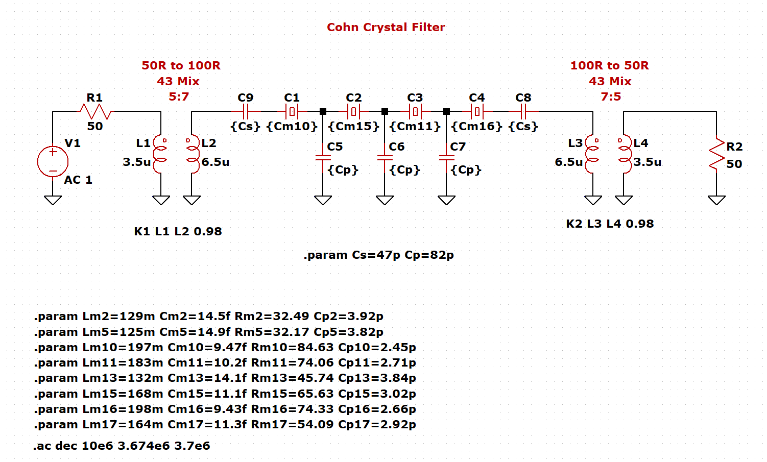
I didn't progress to building the actual filter board after seeing the simulation, and decided to look at other crystals I may have available.
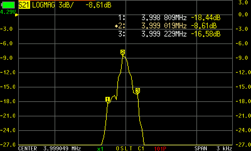
4.0000 MHz Crystals
After seeing the results of the 3.6864 MHz crystals, I decided to try some 4.0000 MHz crystals that I had a handful of. These crystals were a bit more consistent in parameter values.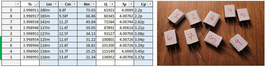
With the consistency of this batch of crystals, I chose to make my filter with them.
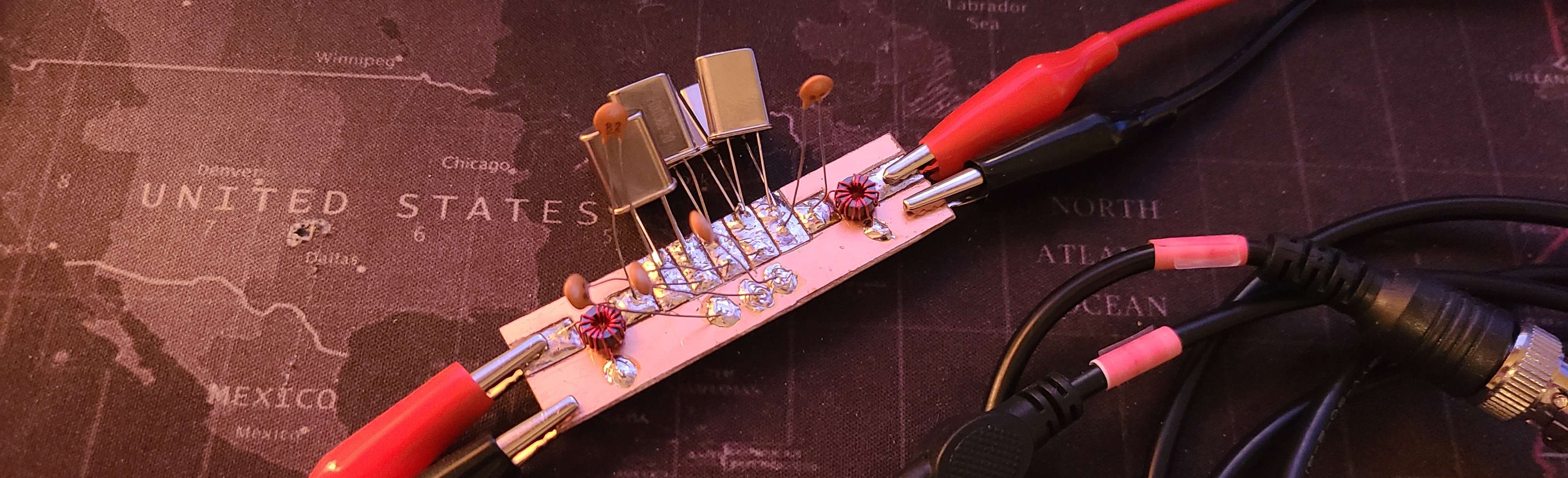
Filter Construction
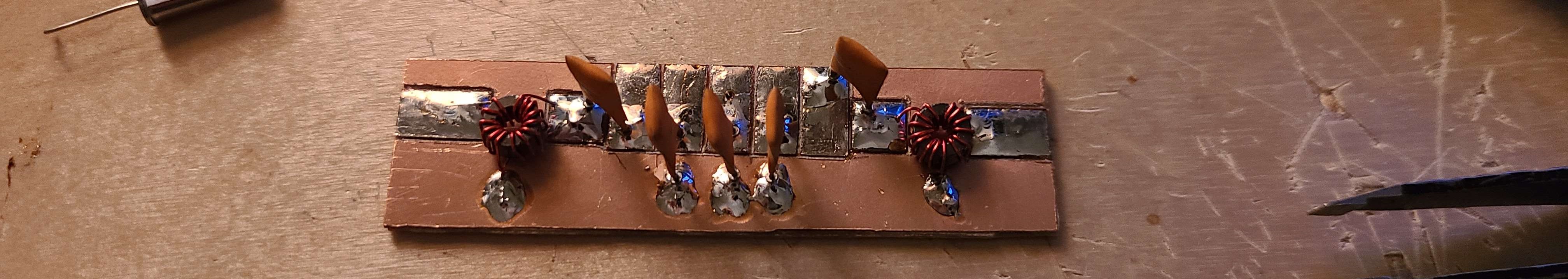
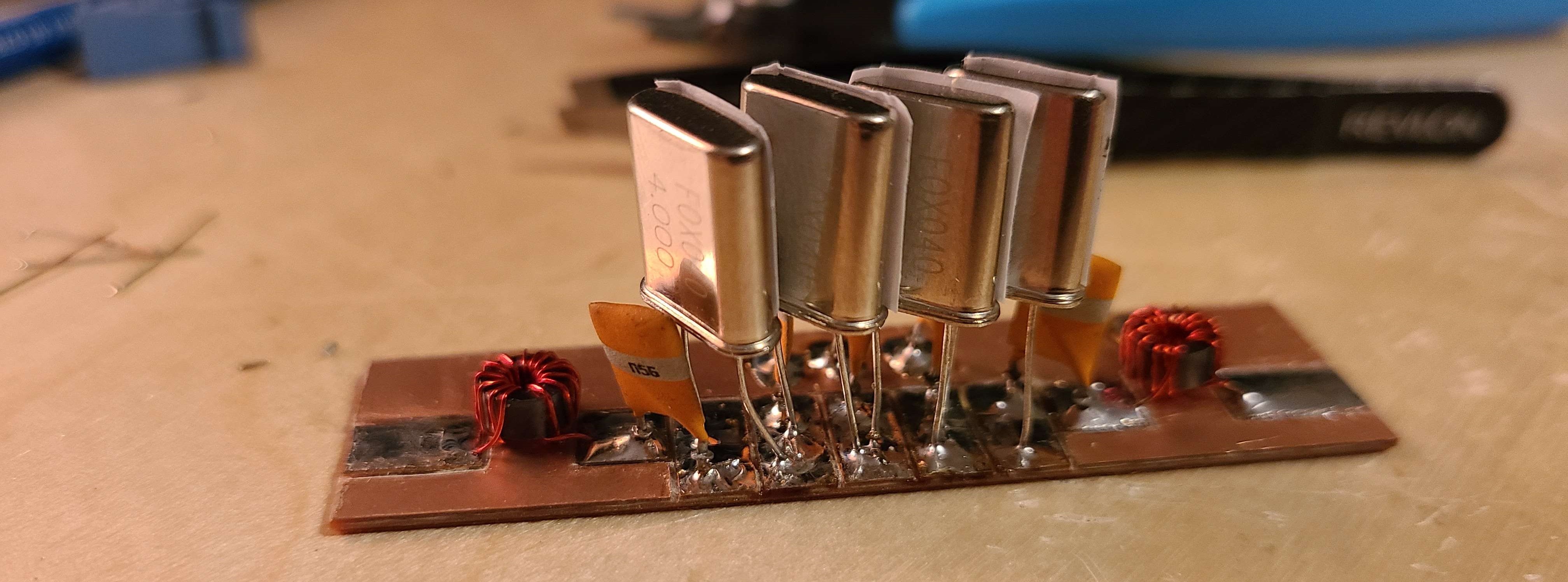
The filter was built using a piece of copper clad board (bakelite substrate). I first scored the tracks I wanted, and prepped the board with some solder. I then soldered the transformers in place and added the capacitors. And finally soldered the crystals onto the board.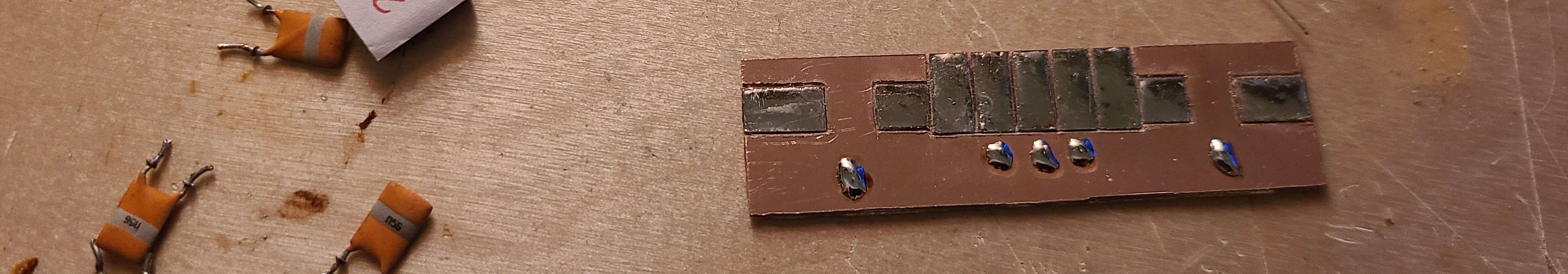
With the filter board built, I tested the filters response using my NanoVNA-F v2. Like the simulation with the 3.6864 MHz crystals, this filter performed terribly. Very bad ripple, and a passband of 420 Hz. This might be passable for a CW filter, but not for an SSB filter like my use case.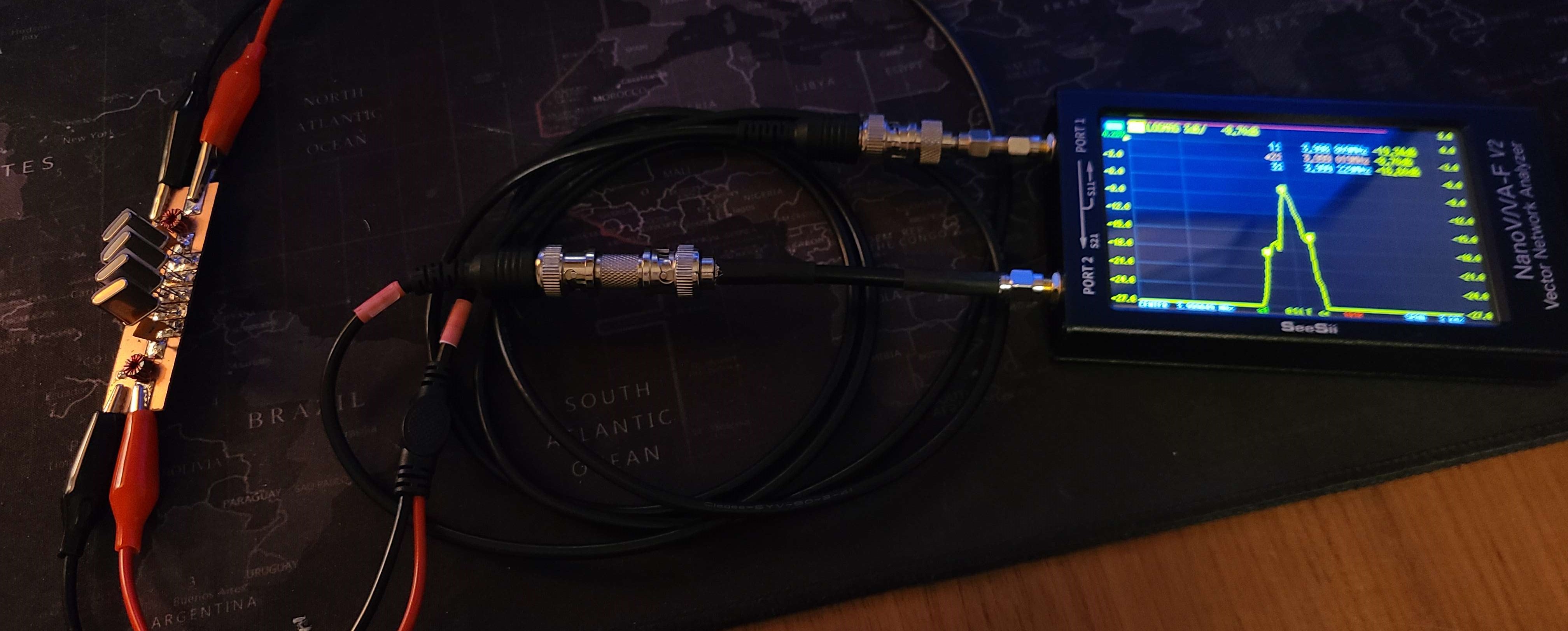
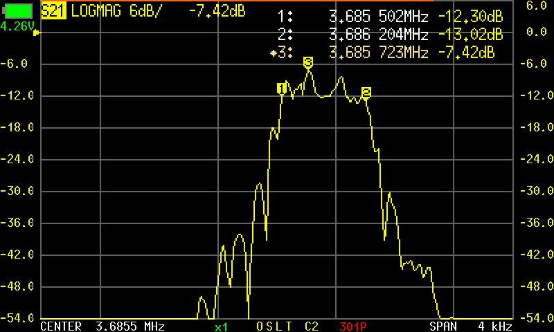
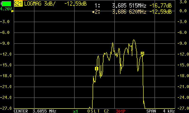
With a response this poor, I began to test different configurations and crystal combinations. This was a bit more of a brute-force approach, and I wasted more than 2 or so hours blindly testing. I started by changing the crystals back to the 3.6864 MHz ones, and used 82 pF capacitors.
This produced a more desirable shape, but had lots of ripple and a passband of only 700 Hz.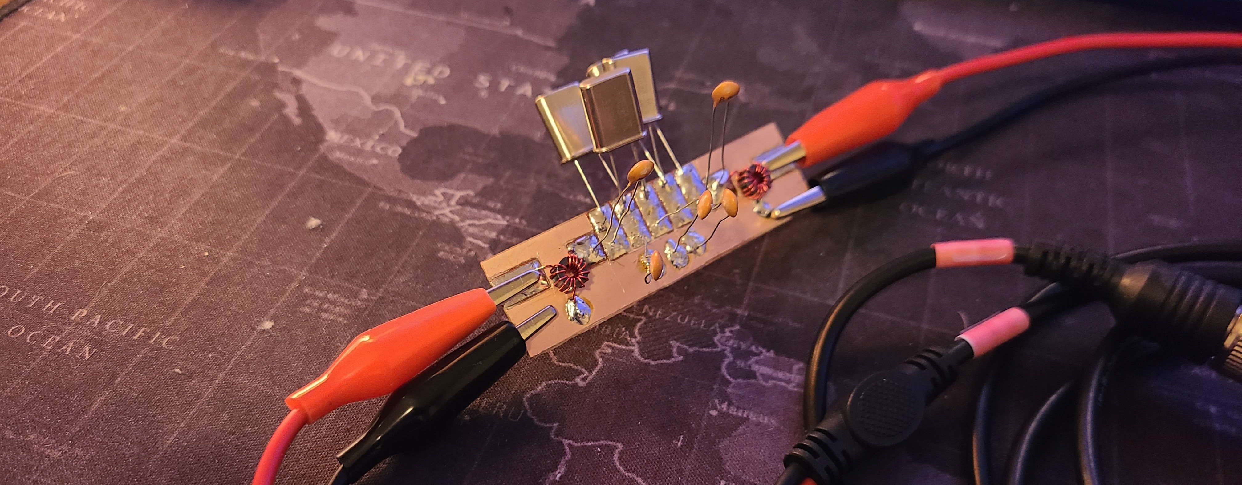
I tested a few other configurations, including putting some crystals in parallel with others. This produced an even more sparradic passband ripple, and overall was a blind shot in the dark.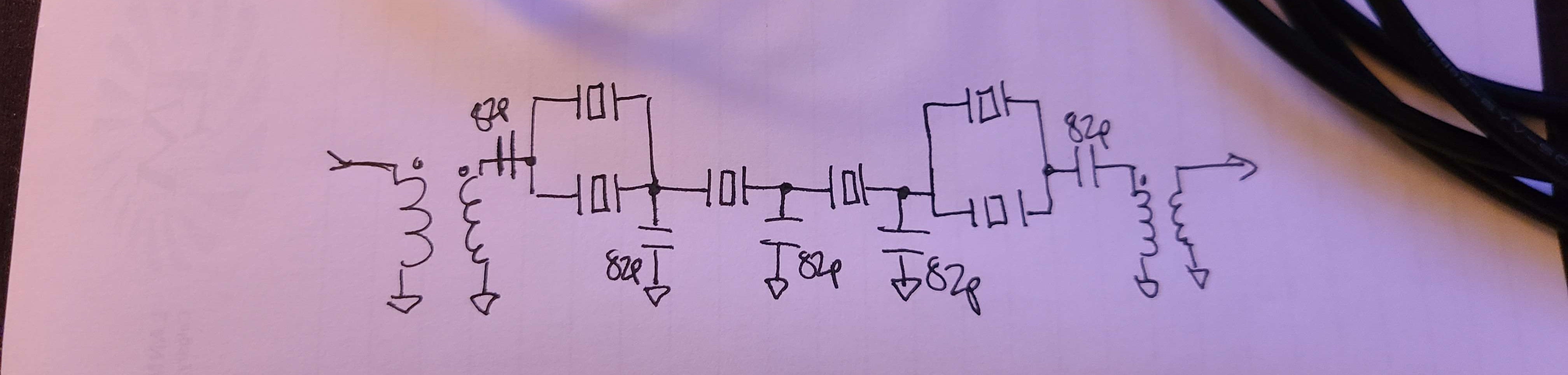
Reason for Poor Performance
After the dissapointing results from this test, I did some additional reading and suspect the poor performance to be because of the impedance mismatch at the input and output of the filter.
The impedance of the cohn filter was assumed to be 100 ohms as that is the first search results provided on google. This however is far from the case, as the impedance may be on the order of 1000 ohms or somewhere in between.
In the next approach to designing this filter I will run some additional simulation, verify the measured crystal parameters by trying different methods, and create some impedance matching networks to properly integrate the filter with the rest of my circuit.
Remarks
Overall, this first approach (more like "attempt") at designing and building a crystal filter wasnt a success, but I still gleaned a good amount of knowledge from it.