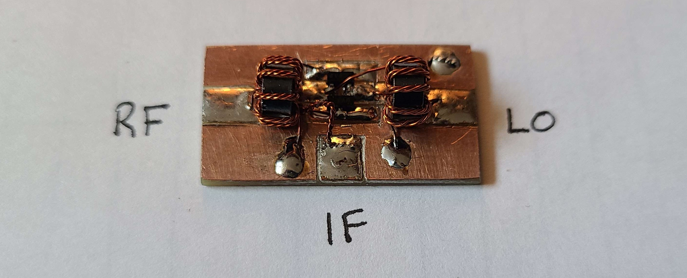
For the 20m superheterodyne reciever, I need two mixers for the RF-IF stage and IF-Audio stage. My initial diode ring mixer design functioned as intended, but this time I chose to make it more compact and to use different diodes. ~ I also built two this time.
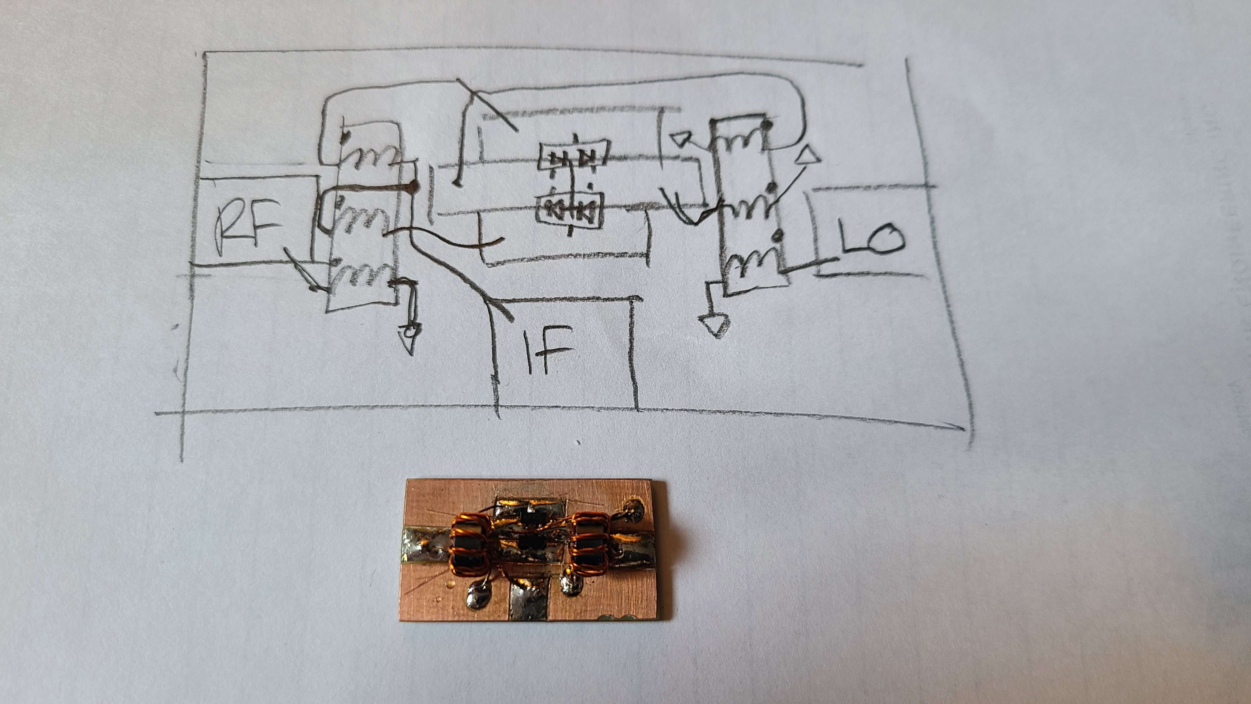
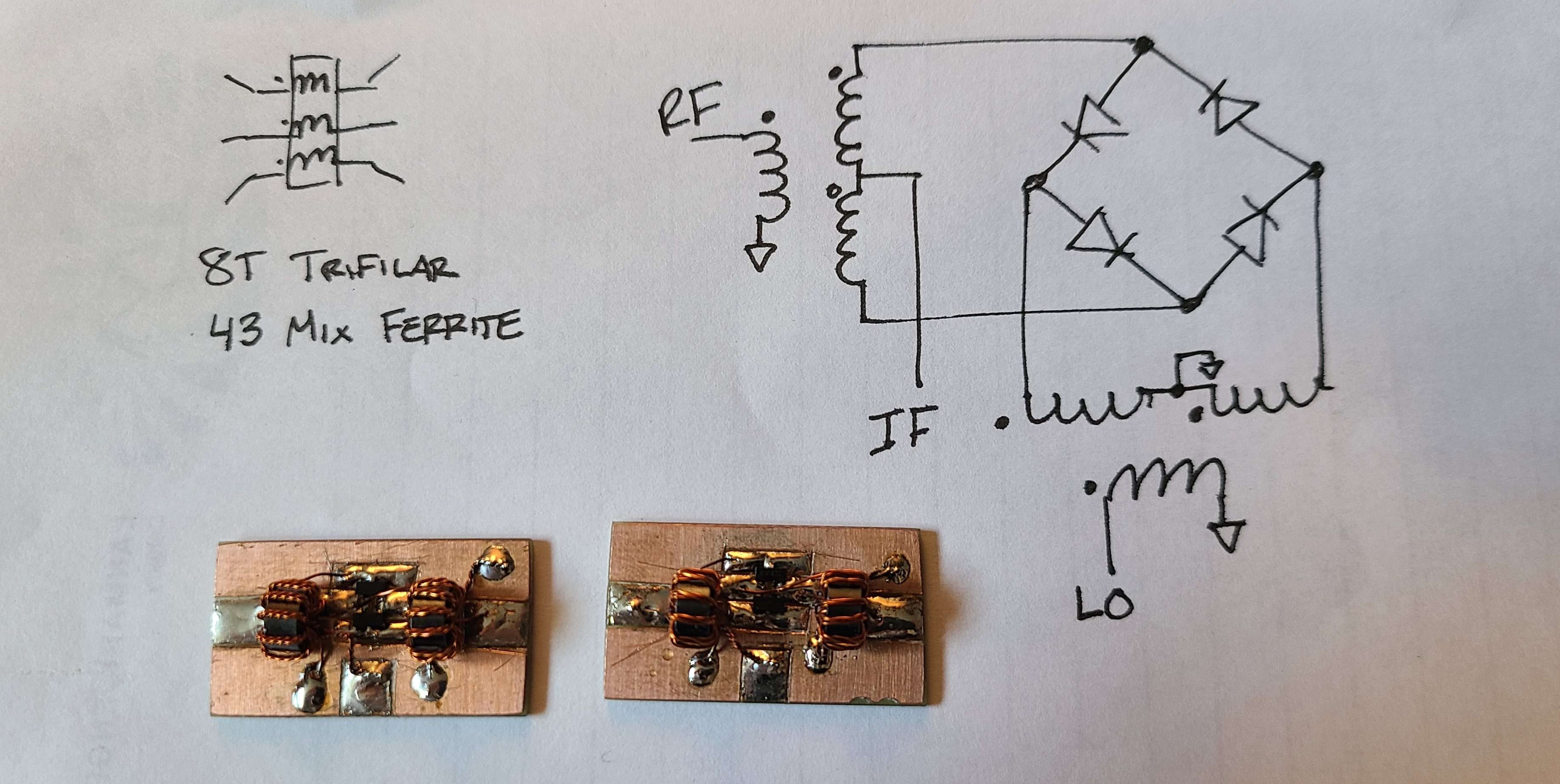
Diode Ring Mixer
Diode Selection
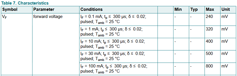
The diodes I used were Nexperia BAT54S. These low forward voltage schottky diodes should reduce the required local oscillator power required to have the mixer operate.
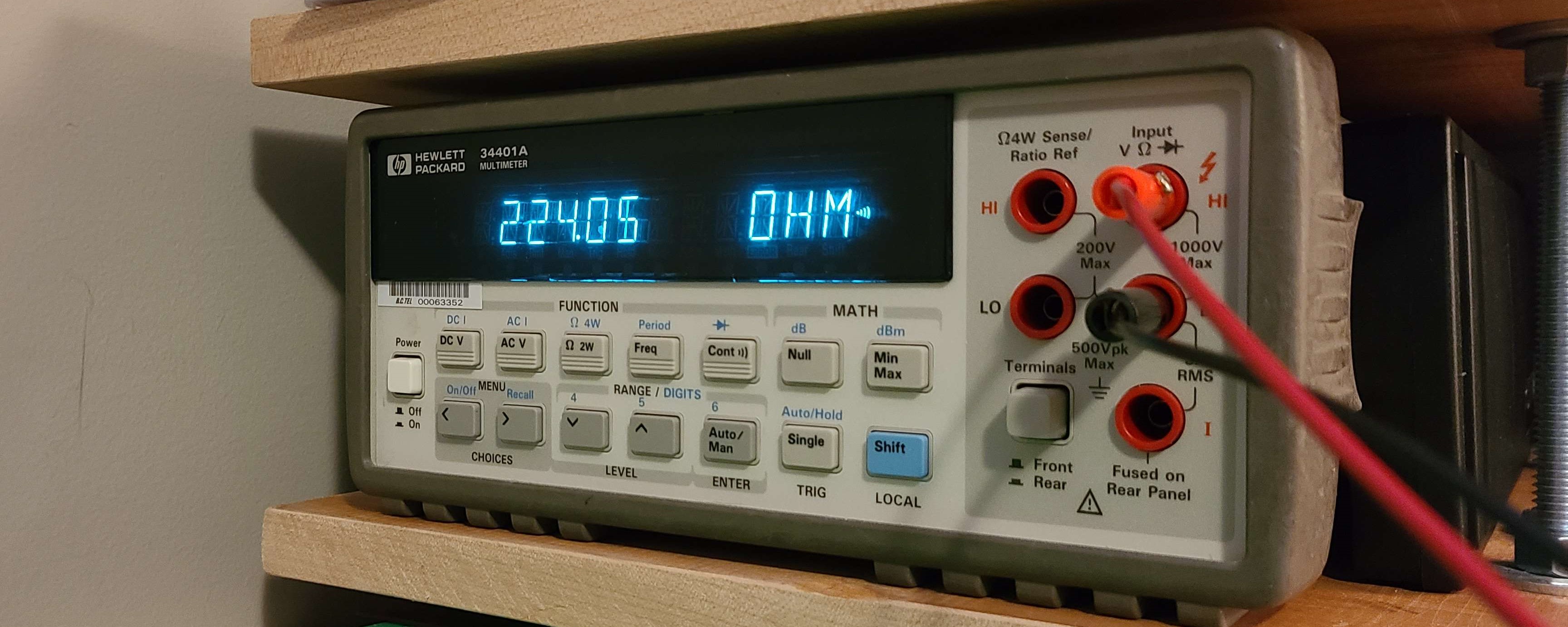
Forward voltage of the BAT54S is (maximum) 320 mV at 1 mA according to its datasheet. When testing on my DMM (at 1 mA) I was measuring around 250 mV.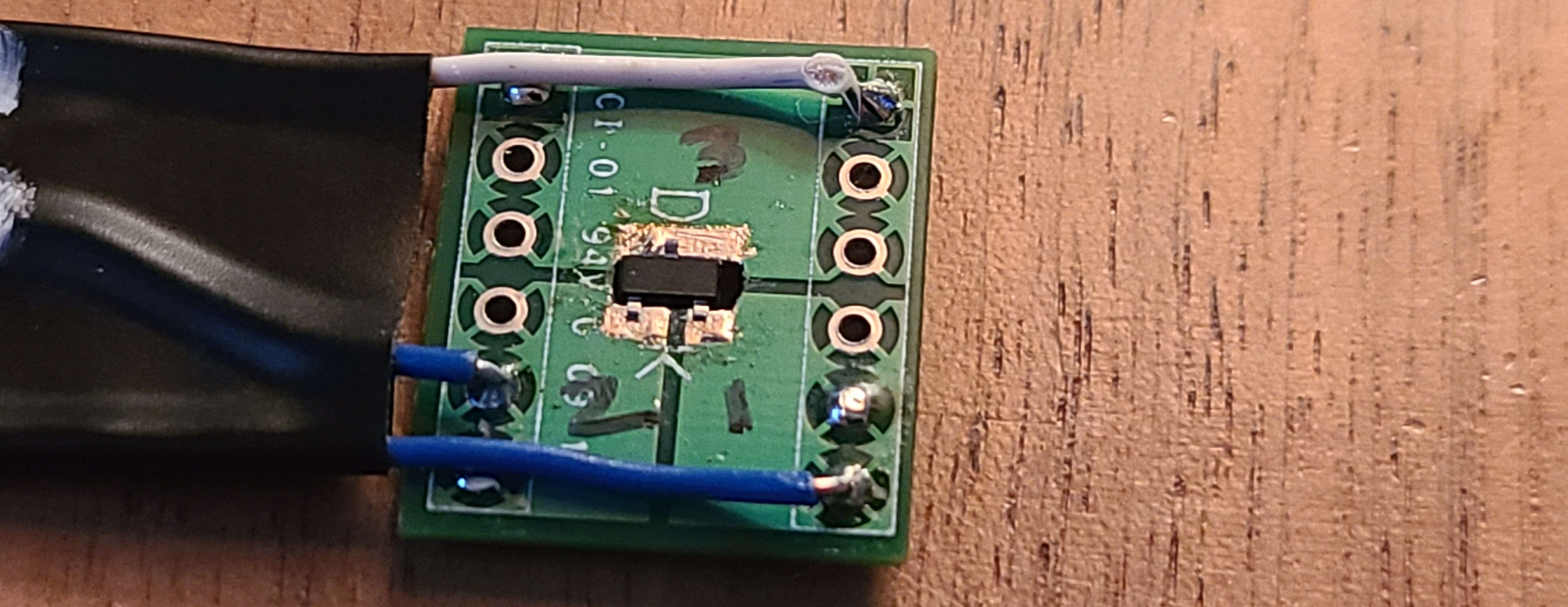
Another reason I switched to the BAT54S was because it has 2 diodes per SOT-23 package. This made for a much more compact desing.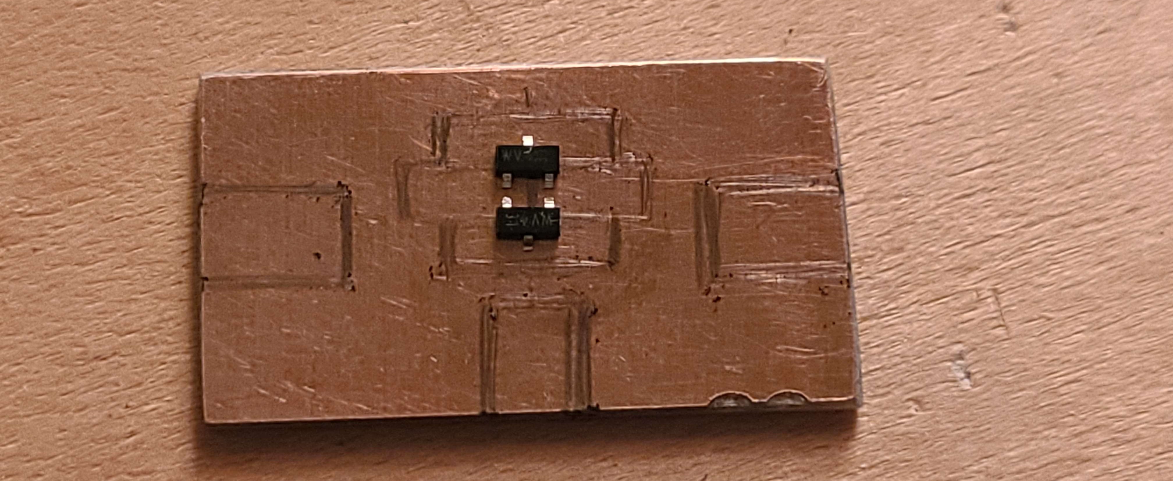
Transformers
The transformers were made similarily to the previous diode ring mixer I made. Twisting 3 equal lengths of 30 AWG wire together, I created 8 trifilar windings around a 43-mix ferrite Fair-Rite 5943000901 toroid.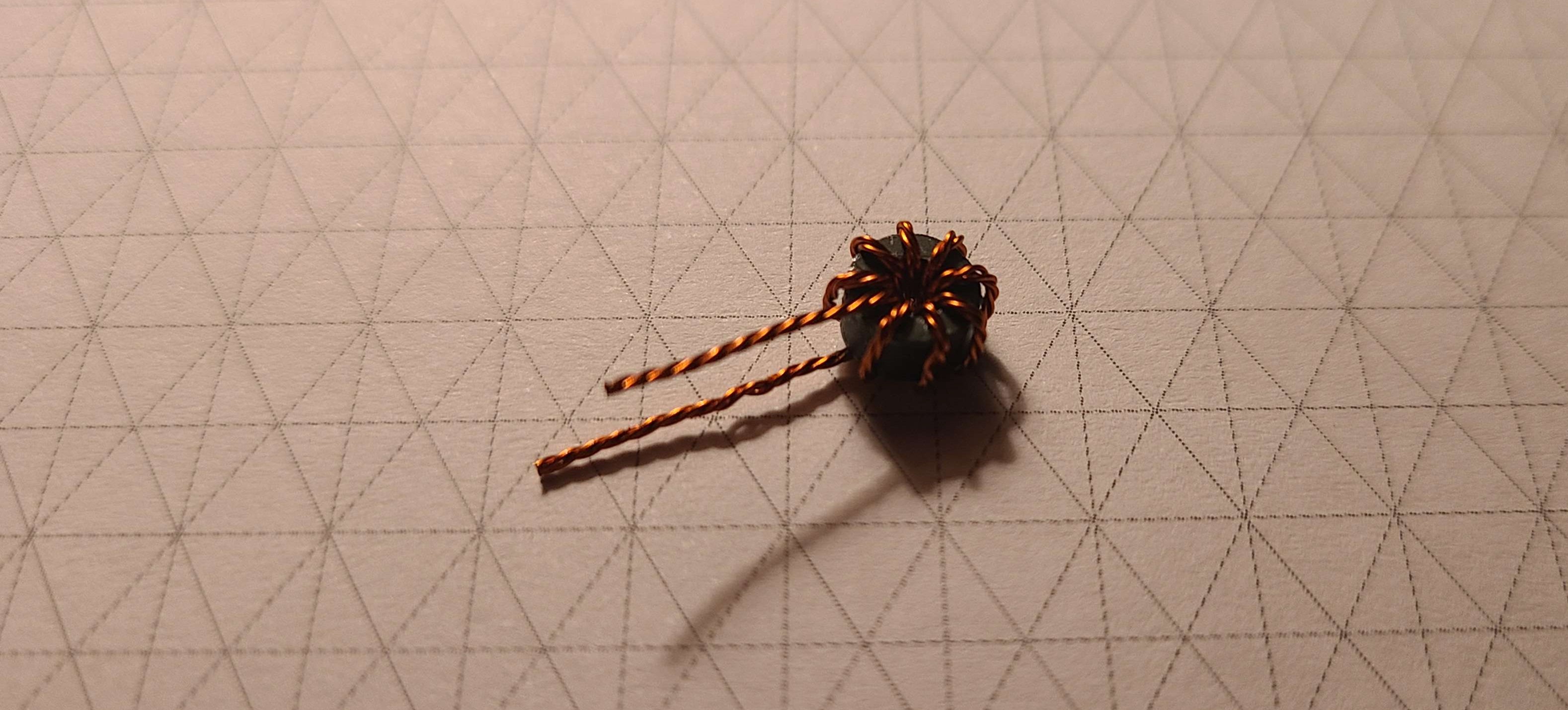
Construction
The diode ring mixers were built on a piece of FR-4 single sided copper clad board, and scored using an exacto knife. The diodes were soldered on first, then the transformers.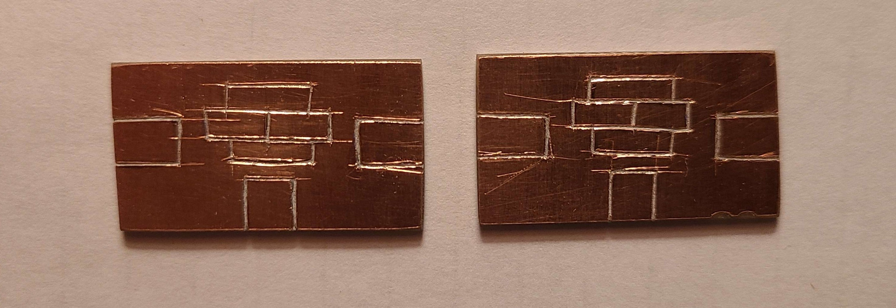
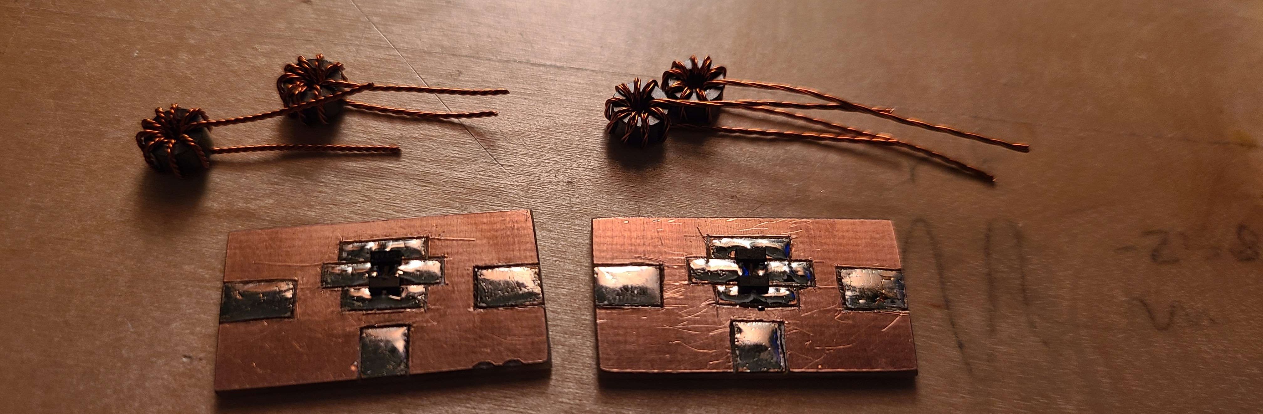
The finished mixers turned out well. After the following images were taken, I added some hot glue to fix the transformers in place.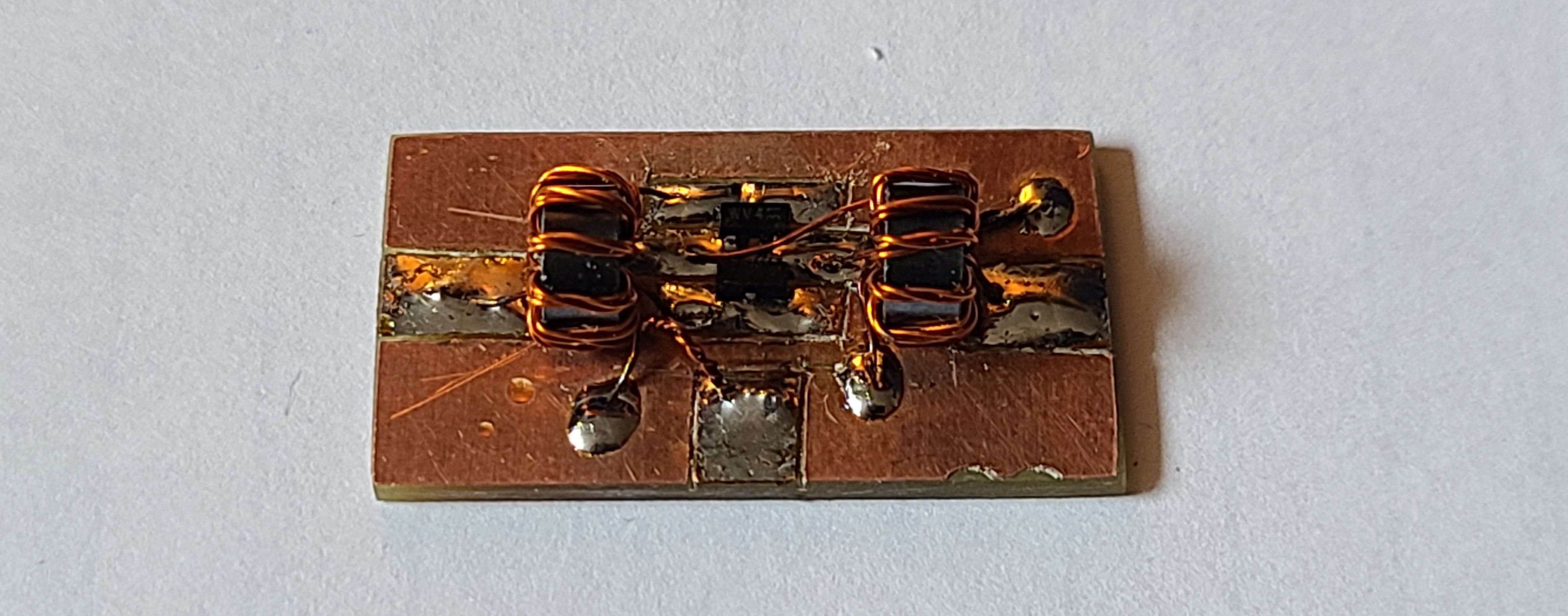
Testing
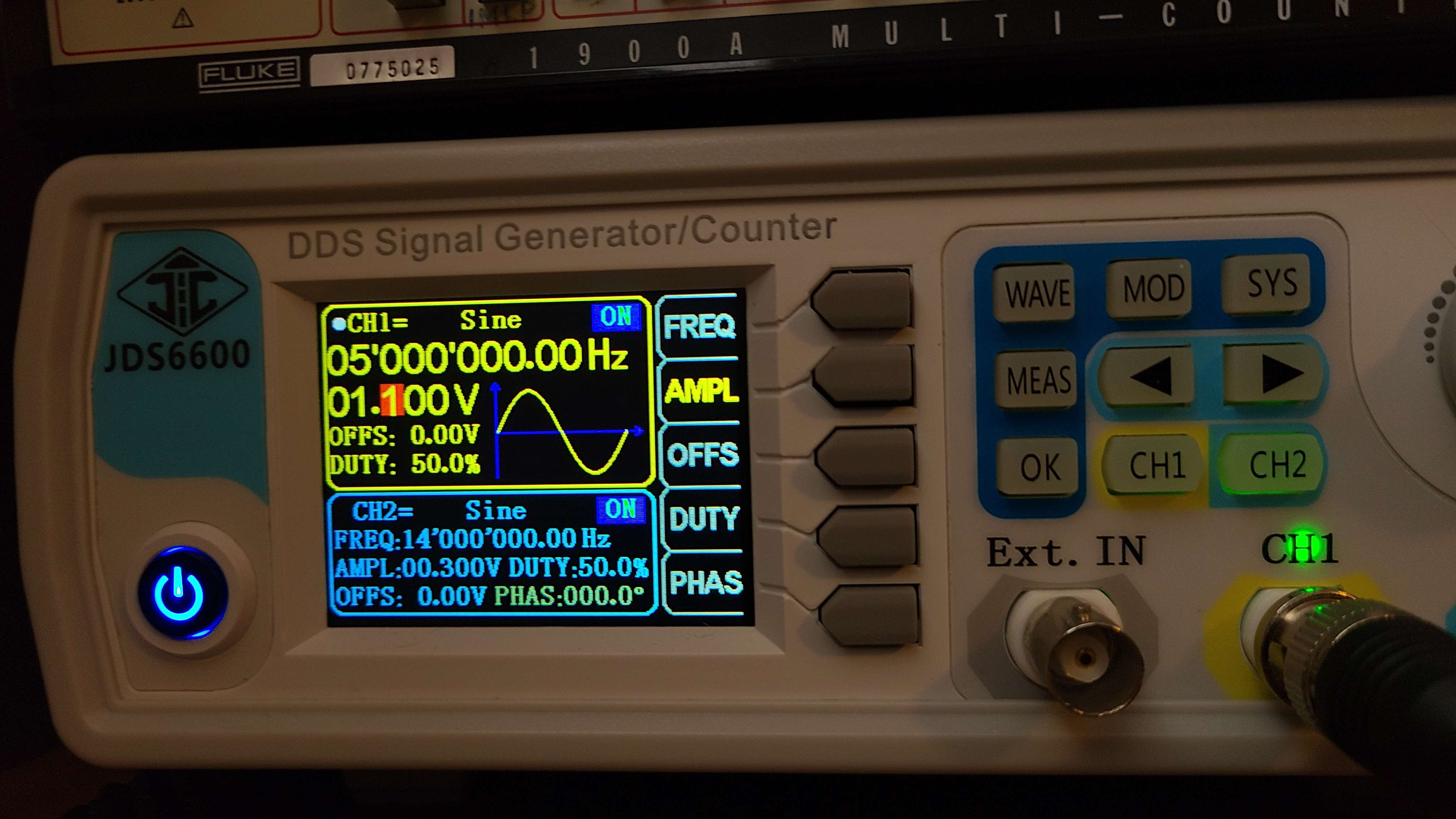
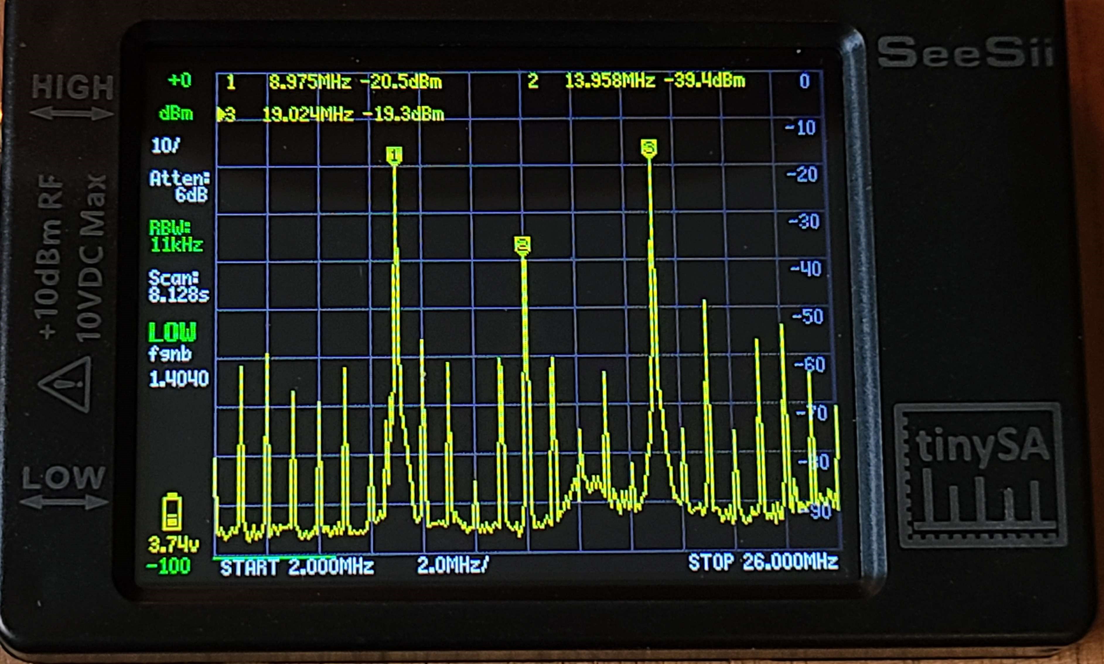
To test the mixer, I set my function generators outputs to be my LO and RF signal. The LO was set to 1.1 Vpp at 5 MHz (assuming a 9 MHz IF) and RF to 0.3 Vpp at 14 MHz. Then using my TinySA I measured the output spectrum.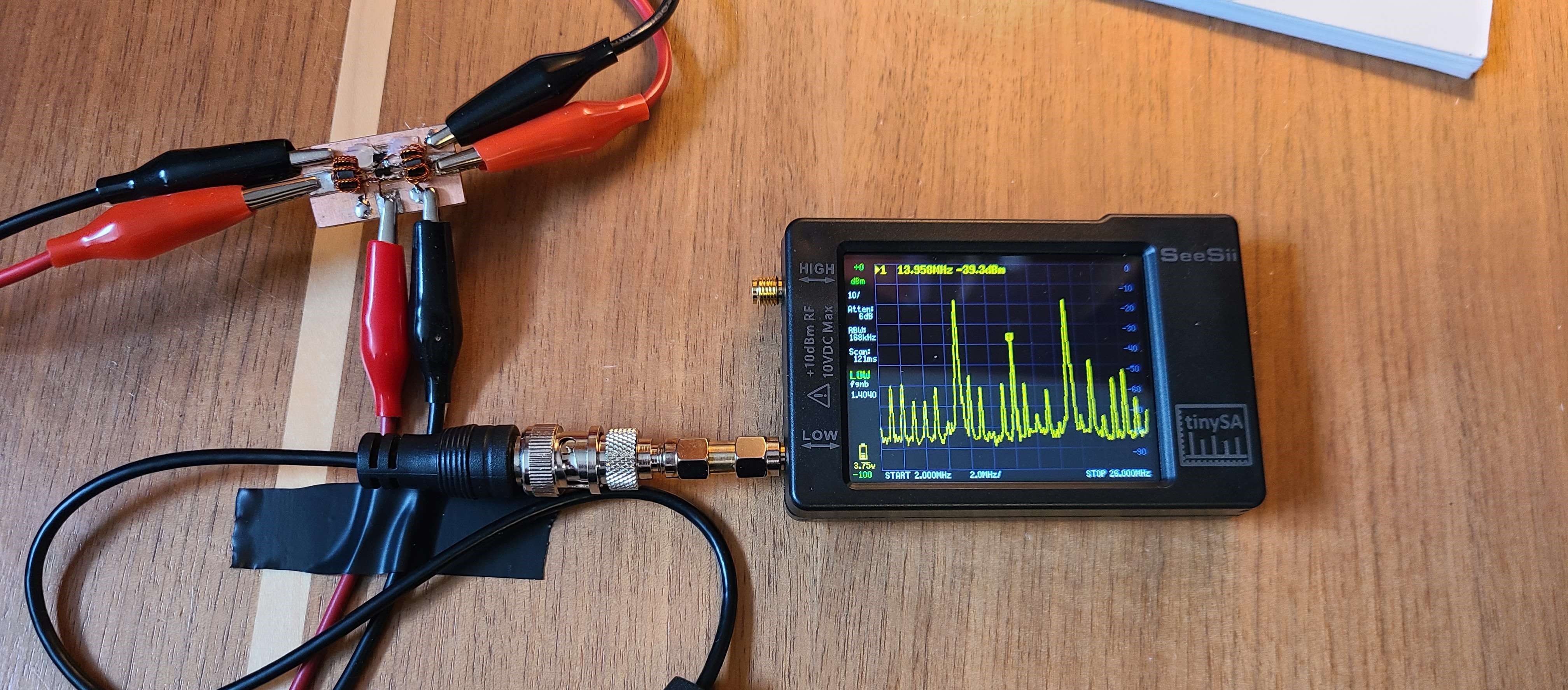
Remarks
These mixers were a break from the crystal filter design I have been doing. With both mixers done, I will redesign the crystal filter for the IF stage.