The next key component of my 20m Superheterodyne Reciever project was the mixer. In a previous post I did some experimentation with a Gilbert cell mixer, which yielded promising results, but there is a simpler approach that requires less components. This brings us to the double balanced diode ring mixer (or double balance mixer, DBM for short).
Design
The diode ring DBM is a switching type mixer, where the LO drives the diodes in the ring to be in an on or off state. The design of this mixer is fairly straight forward as the only components needed are 4 matched diodes and two transformers.
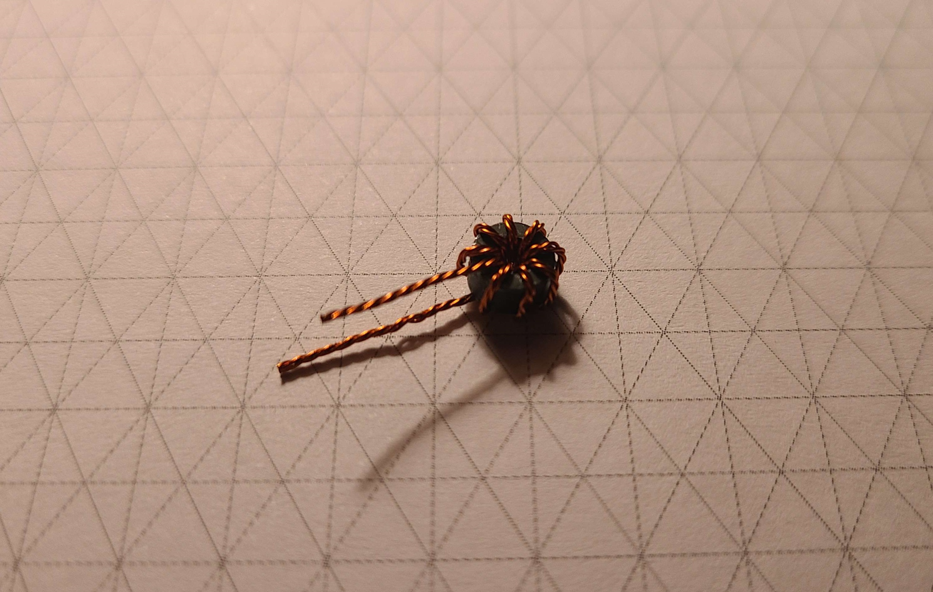
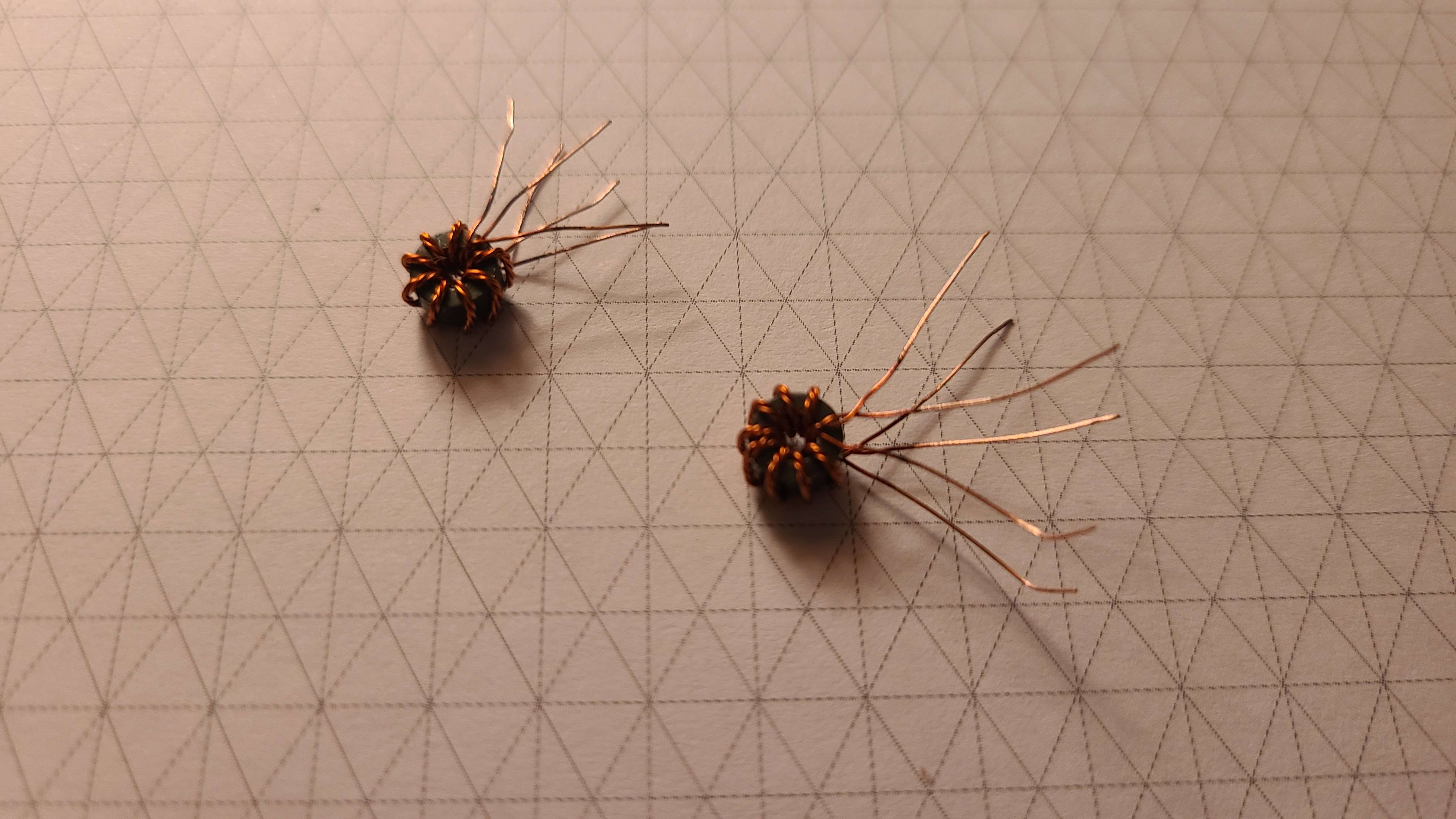
Creating the Transformers
The first component that needs to be built is the transformers. To do this I need both the right core material and wire.
For the wire, I used 30 AWG enameled wire. Being that this is a 3 winding transformer, I twisted the wires of the 3 windings to reduce the leakage inductance and maintain balance between all 3. As far as I am aware, this is known as trifilar winding (which is similar to bifilar winding but with a third wire).
Once I had my wire ready for the transformers I needed to choose the right core material. For this I chose 43 mix ferrite toroids (Fair-Rite PN:5943000901) as they provided a high inductance with low loss at the frequency I was operating at.
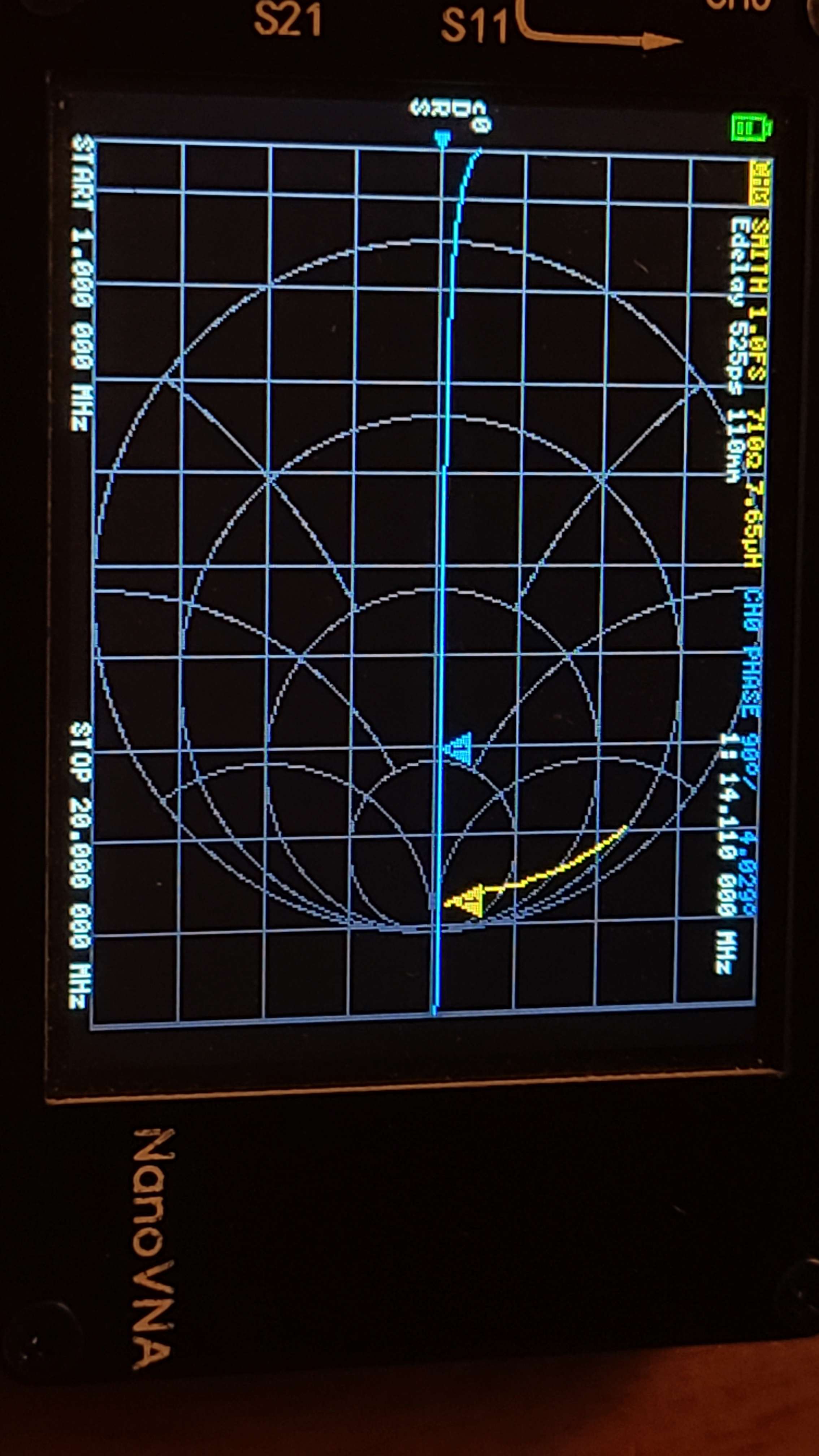
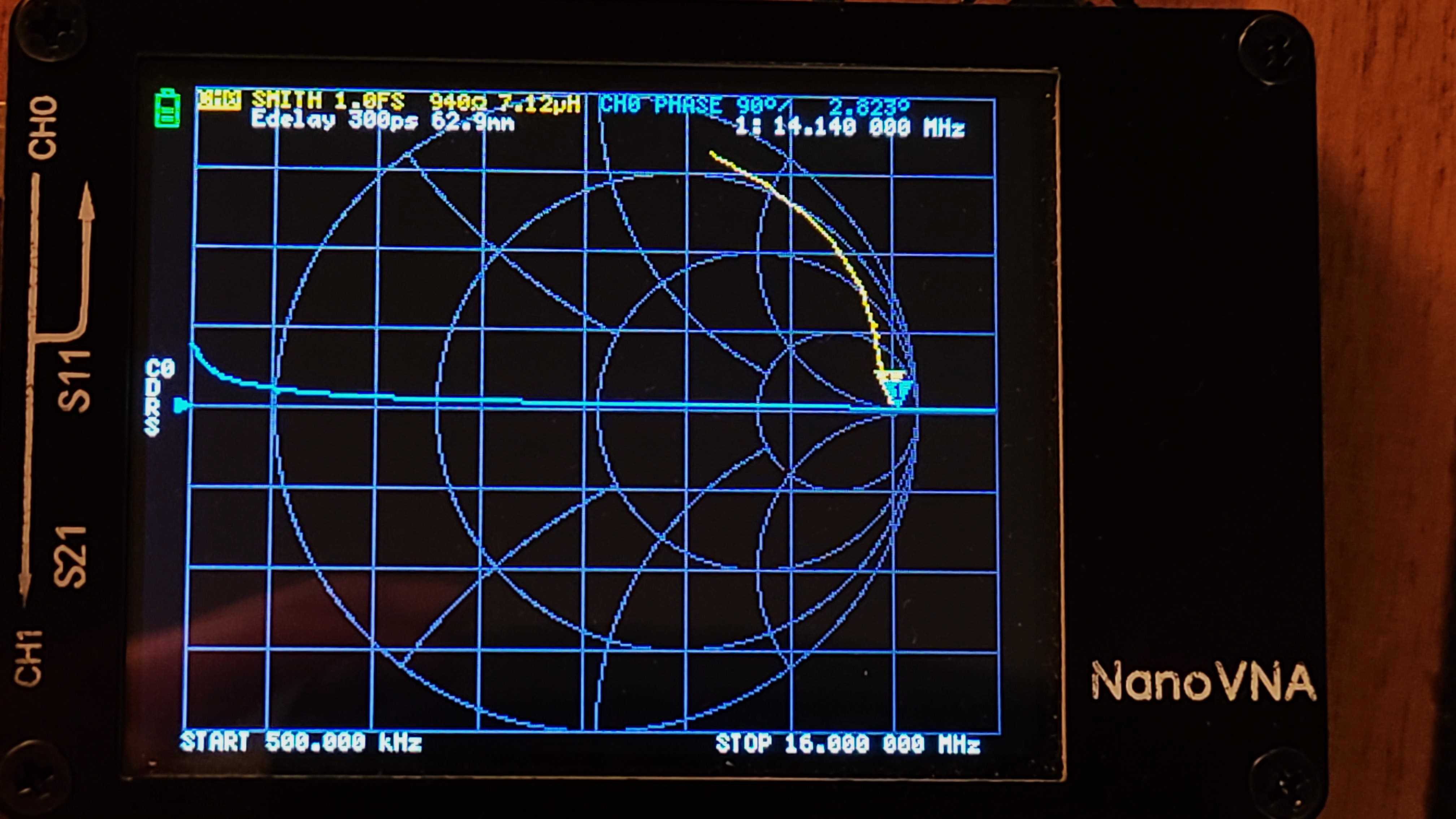
The target inductance was 7 uH as that provides a large enough impedance at 14 MHz. To achive this I need to wind 8 turns.
With the transformers complete, I verified that they were within the target value range.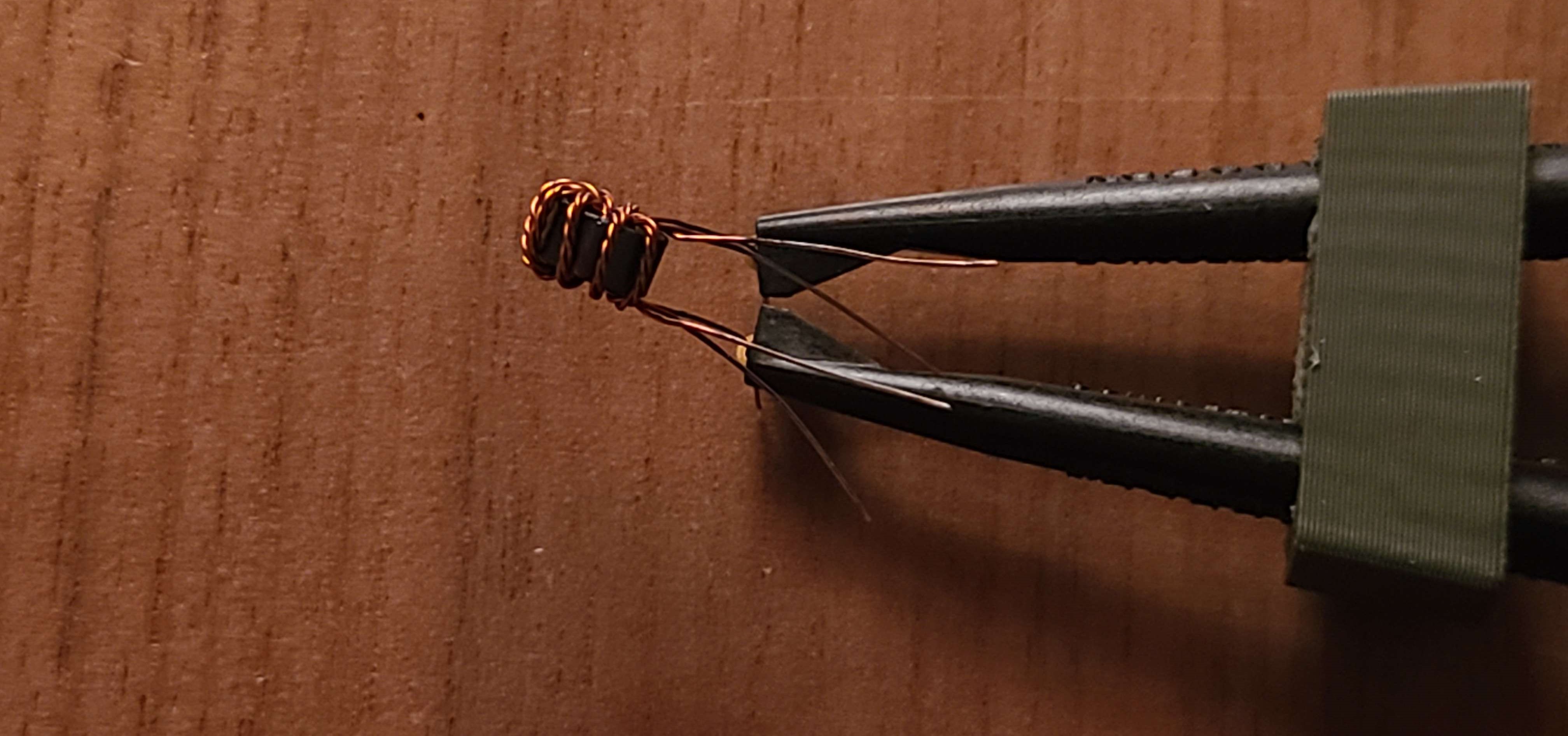
Binning the Diodes
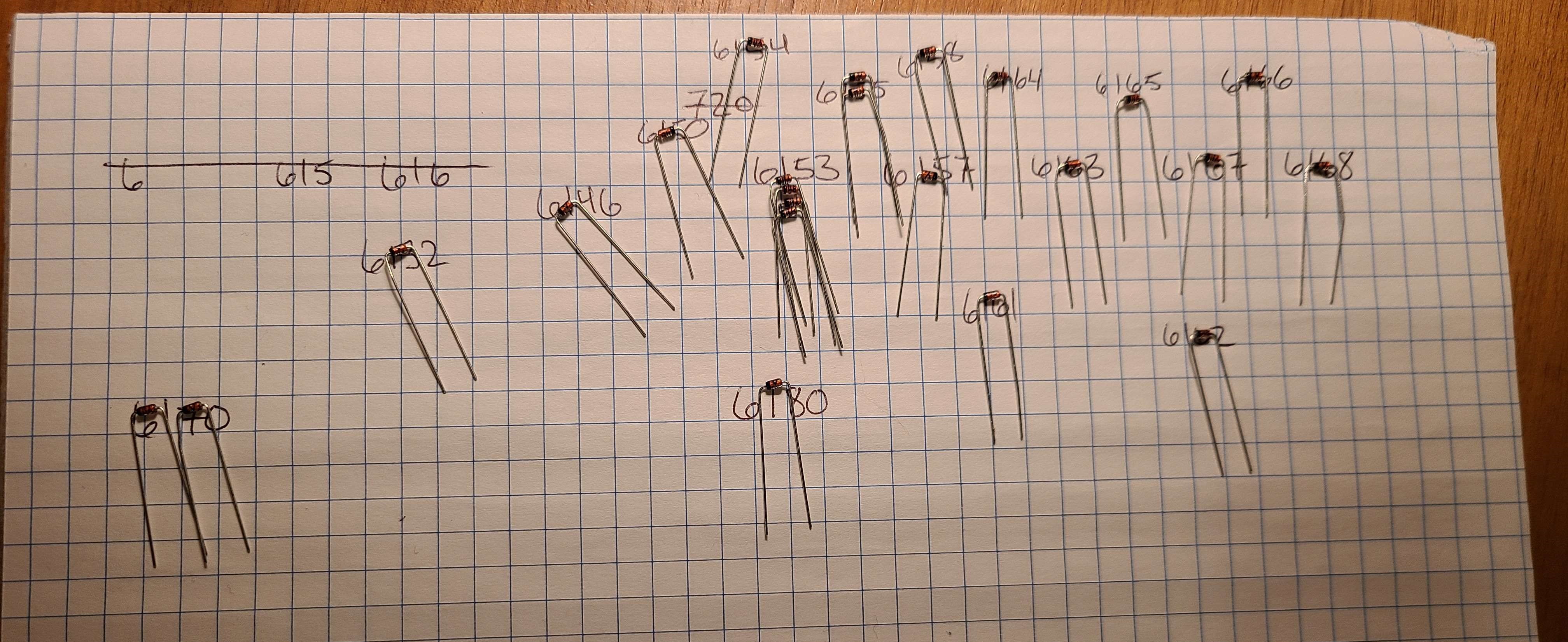
Up next are the diodes. I chose the 1N4148 diode as they are plentiful (as in I have more than I will ever be able to use).
Using the diode test function on my DMM, I was able to bin the diodes based on the voltage drop down to 0.0001 V. This is of course overkill, but since I was able to, I did it anyway.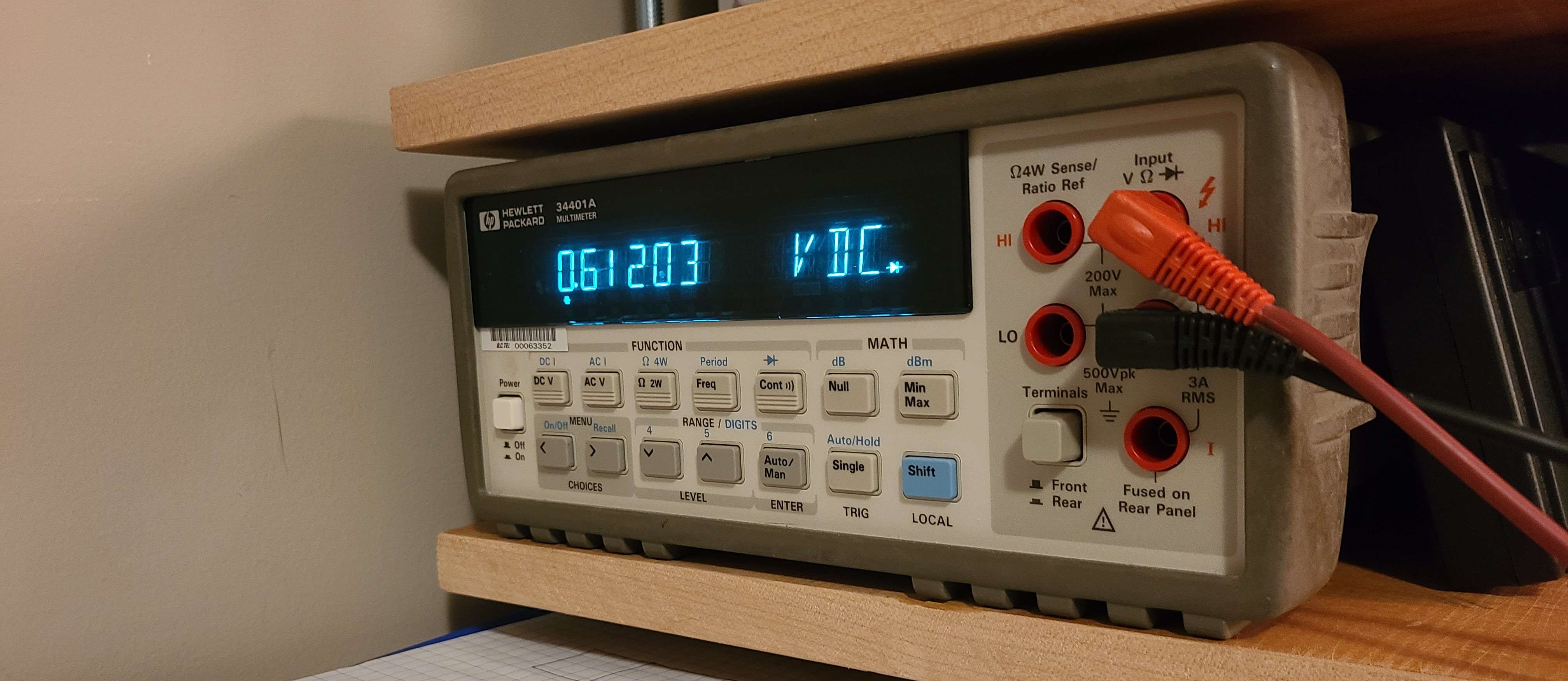
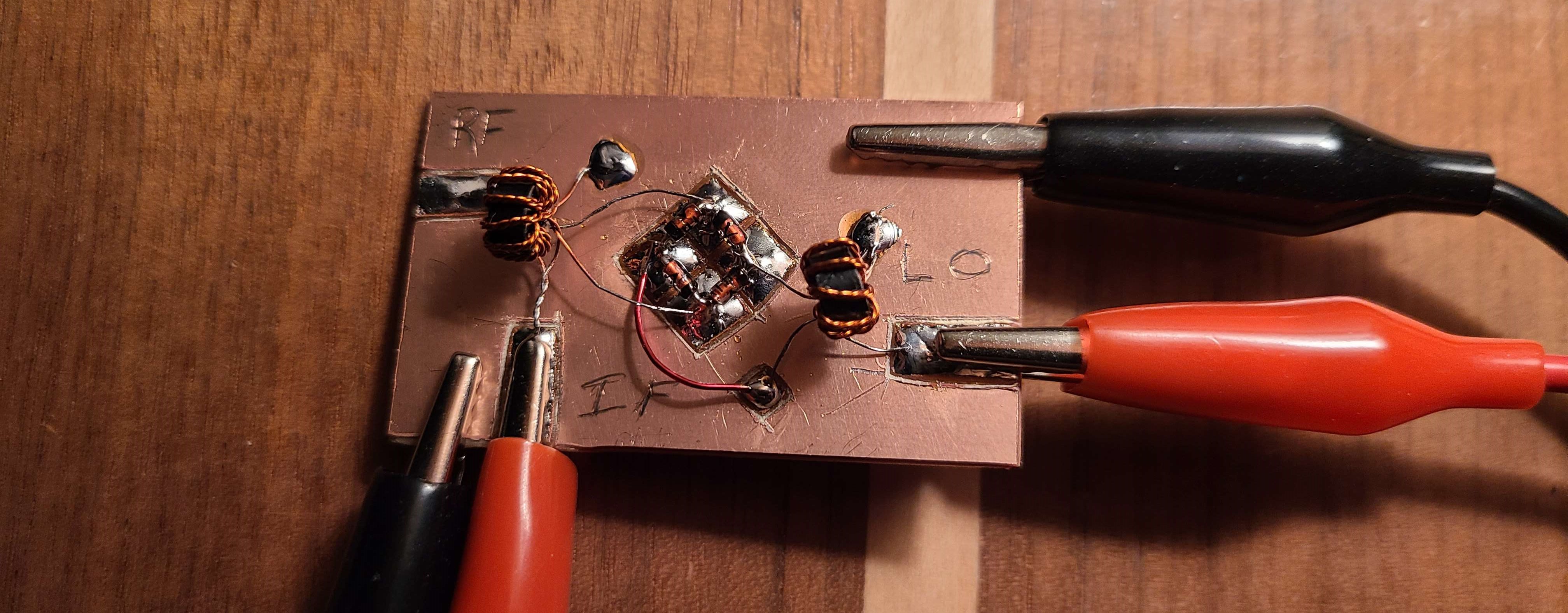
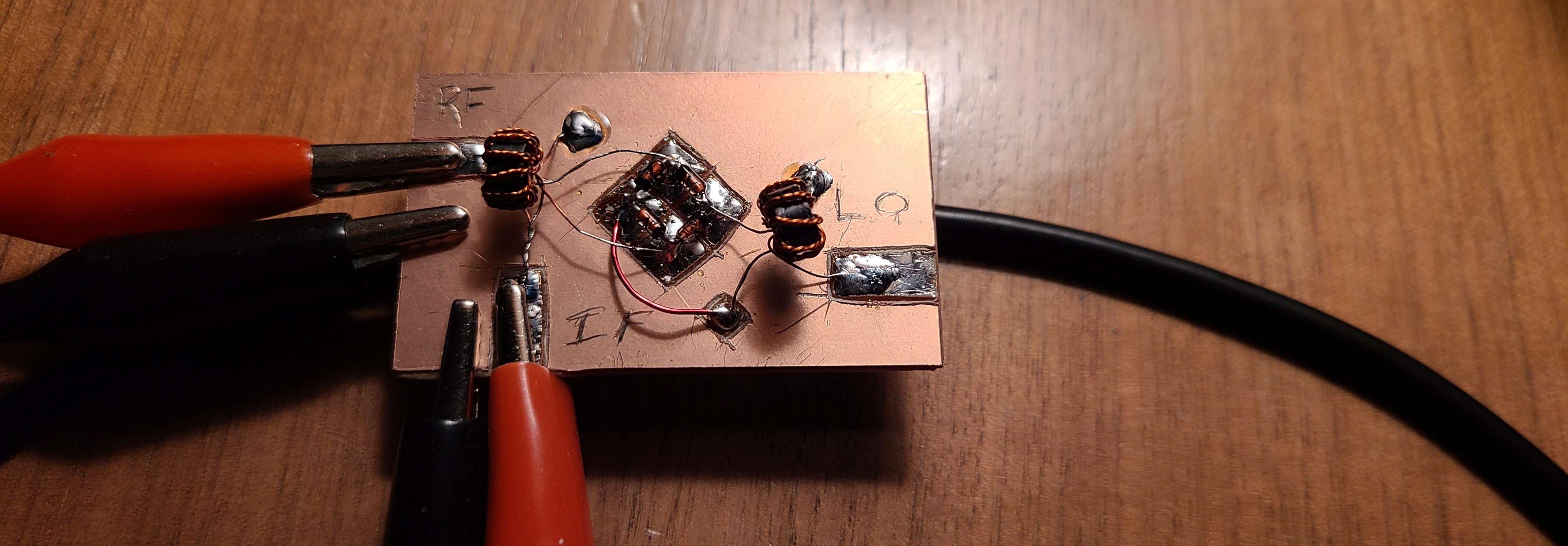
Building the Mixer
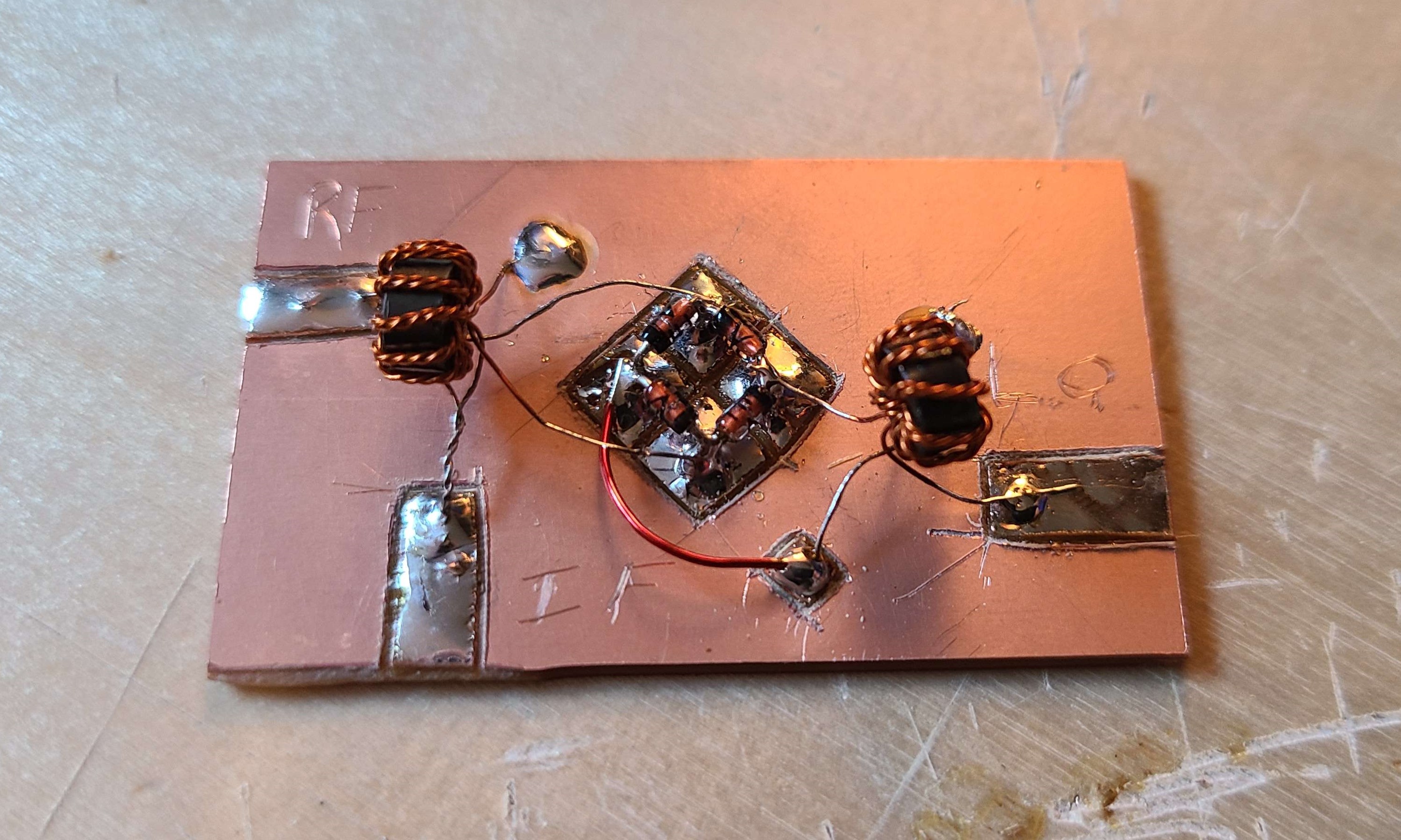
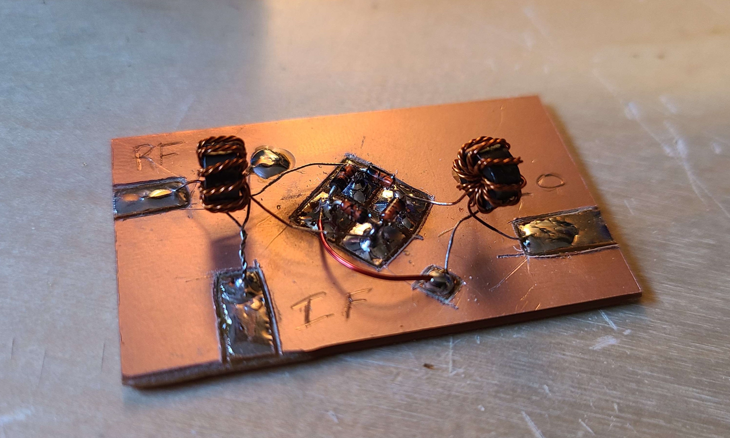
All that was left was to take all the components and solder them together. I soldered everything to a piece of copper clad board with a bakelite substrate.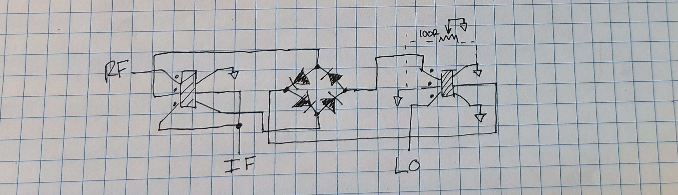
Testing the Mixer
Once the mixer was built, I tested its functionality using the function generator, oscilloscope, and spectrum analyzer.
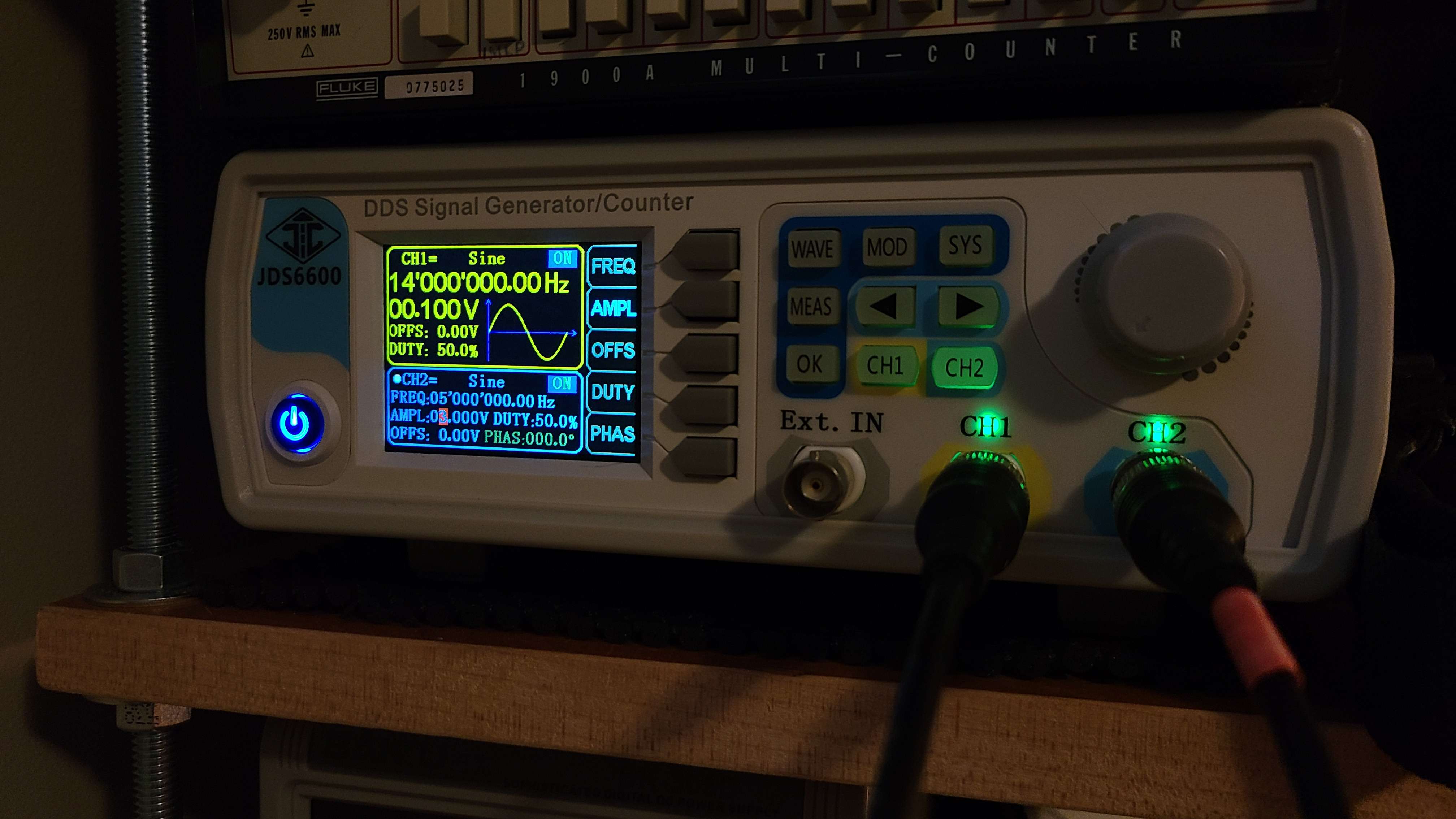
I set the function generator to output a 0.1 Vpp 14 MHz RF signal on channel 1, and a 5 MHz LO signal on channel 2. With a diode ring mixer, the LO needs to be at a high enough voltage to drive the diodes into an on state, so I set it to 3 Vpp.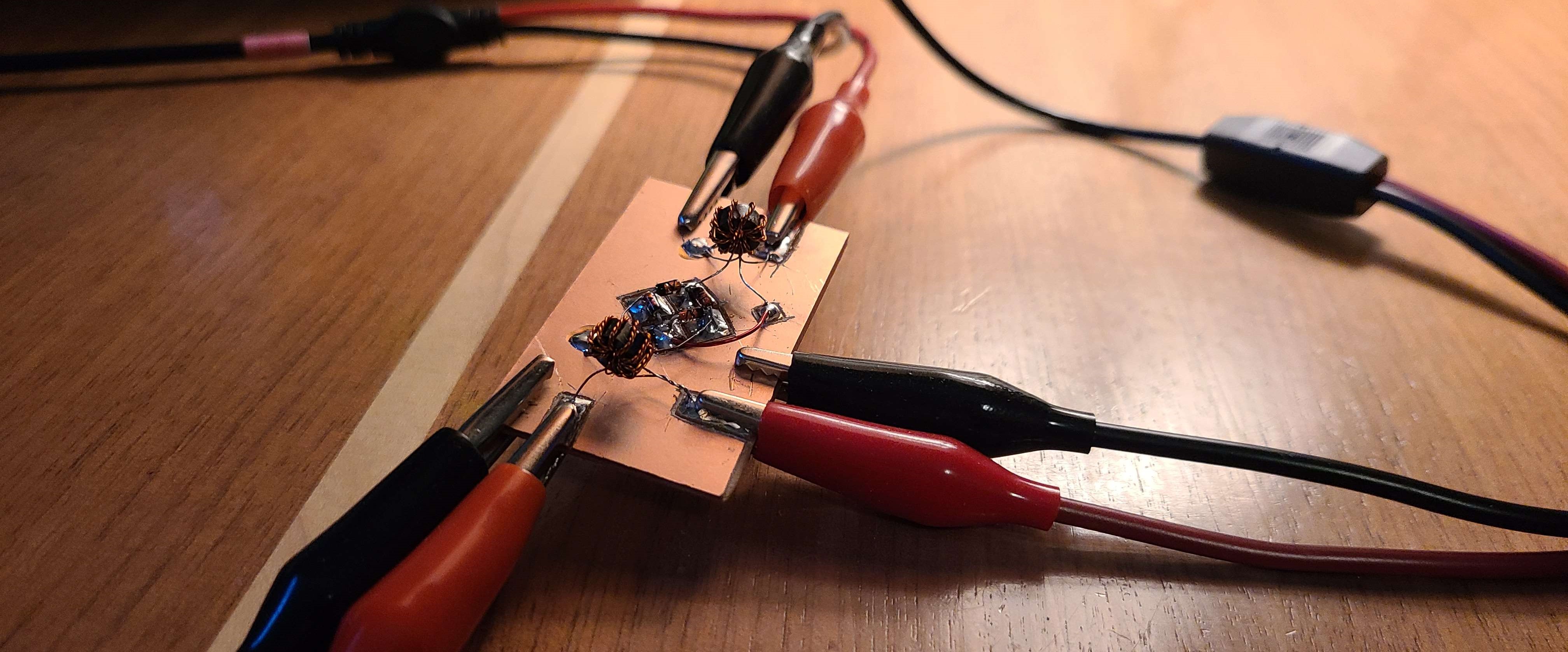
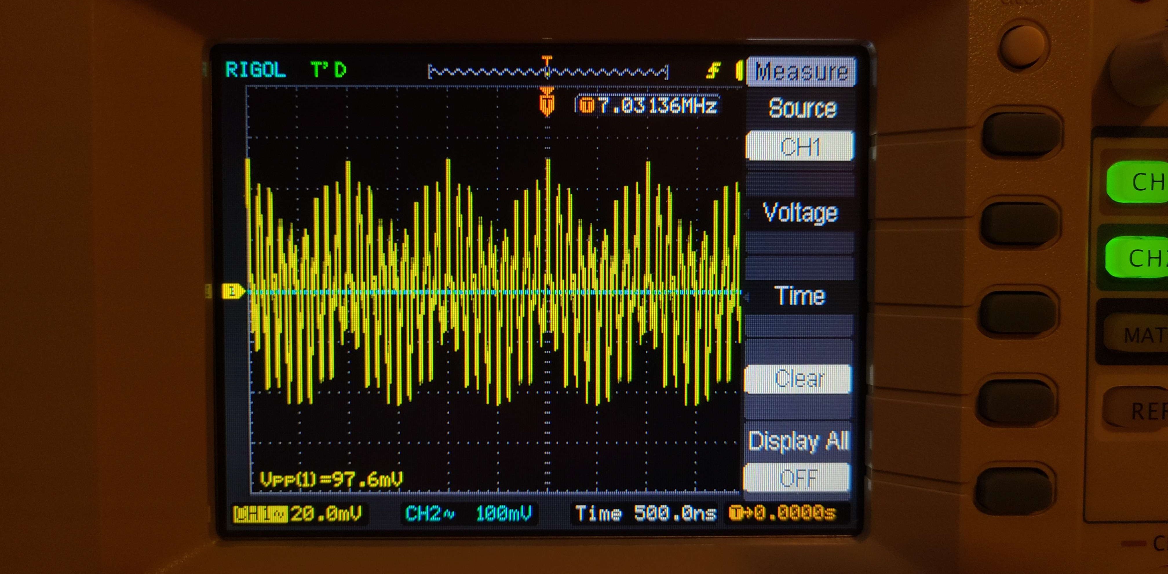
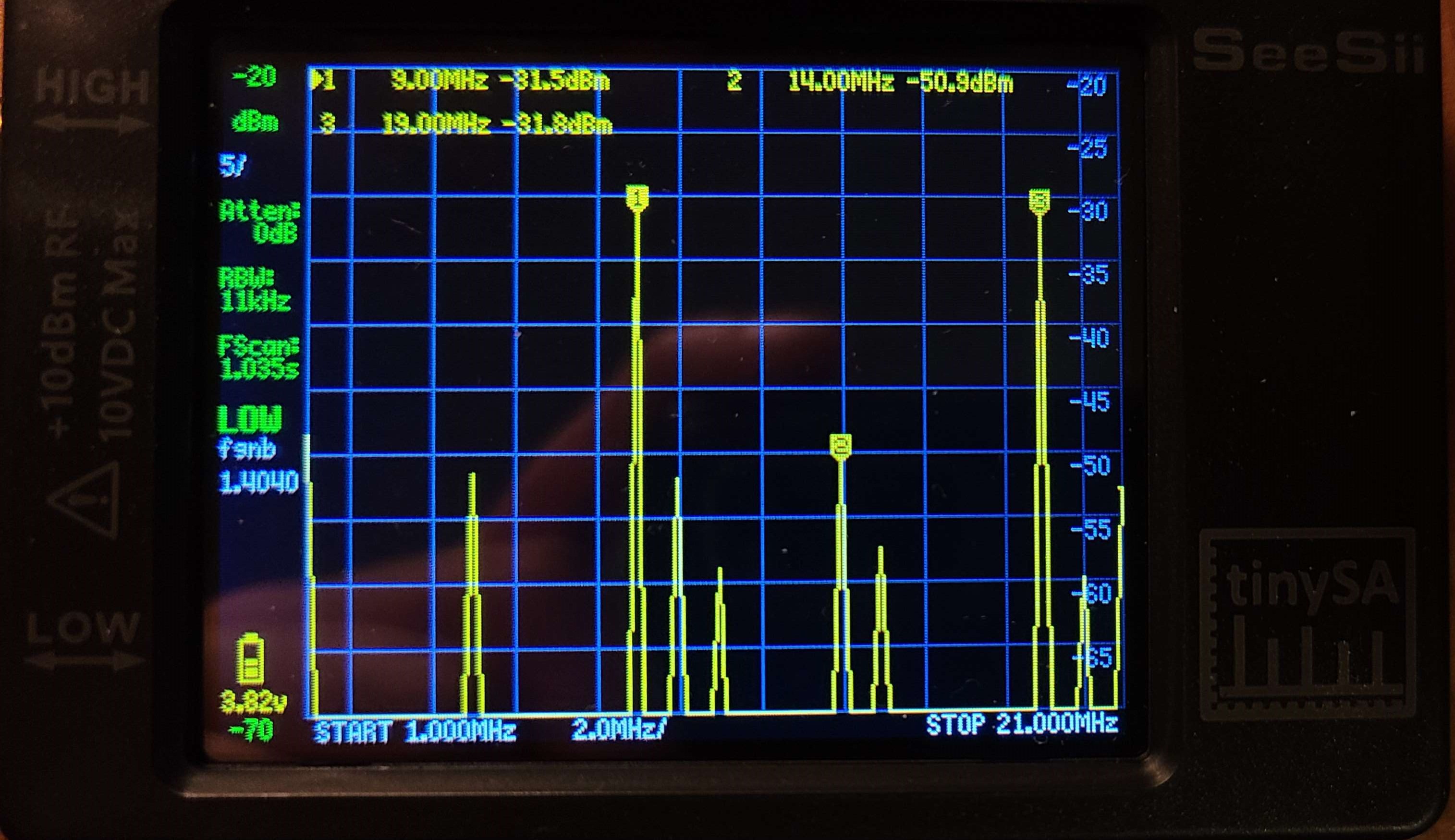
Using the oscilloscopes FFT functionality and the TinySA spectrum analyzer, I looked at the spectrum output of the mixer. The peak shown on the oscilloscopes FFT is the 9 MHz product of the mixer (f_RF - f_LO = f_IF).
The TinySA measurement shows the RF signal is about 20 dB lower than the two products, which is quite acceptable.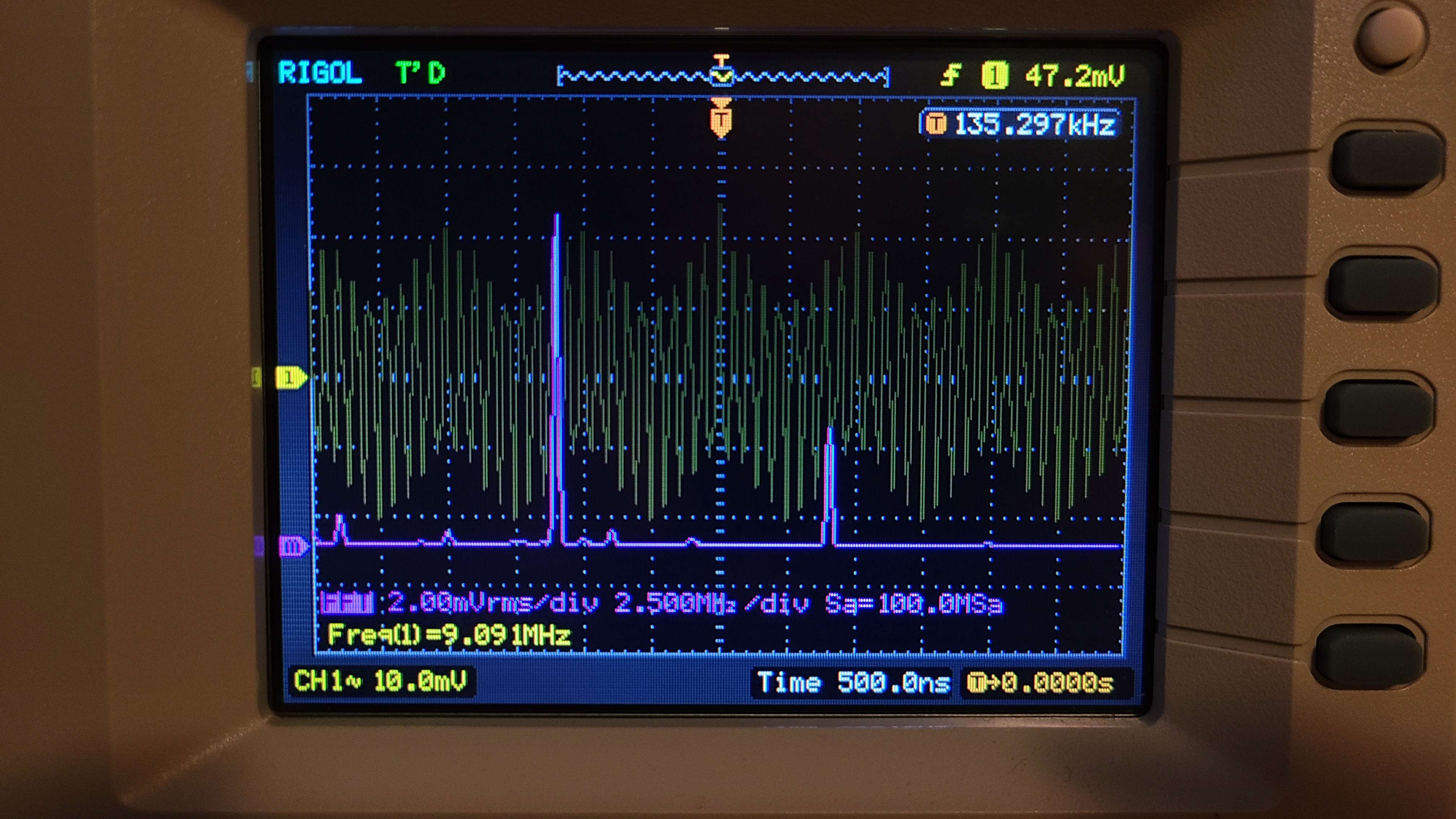
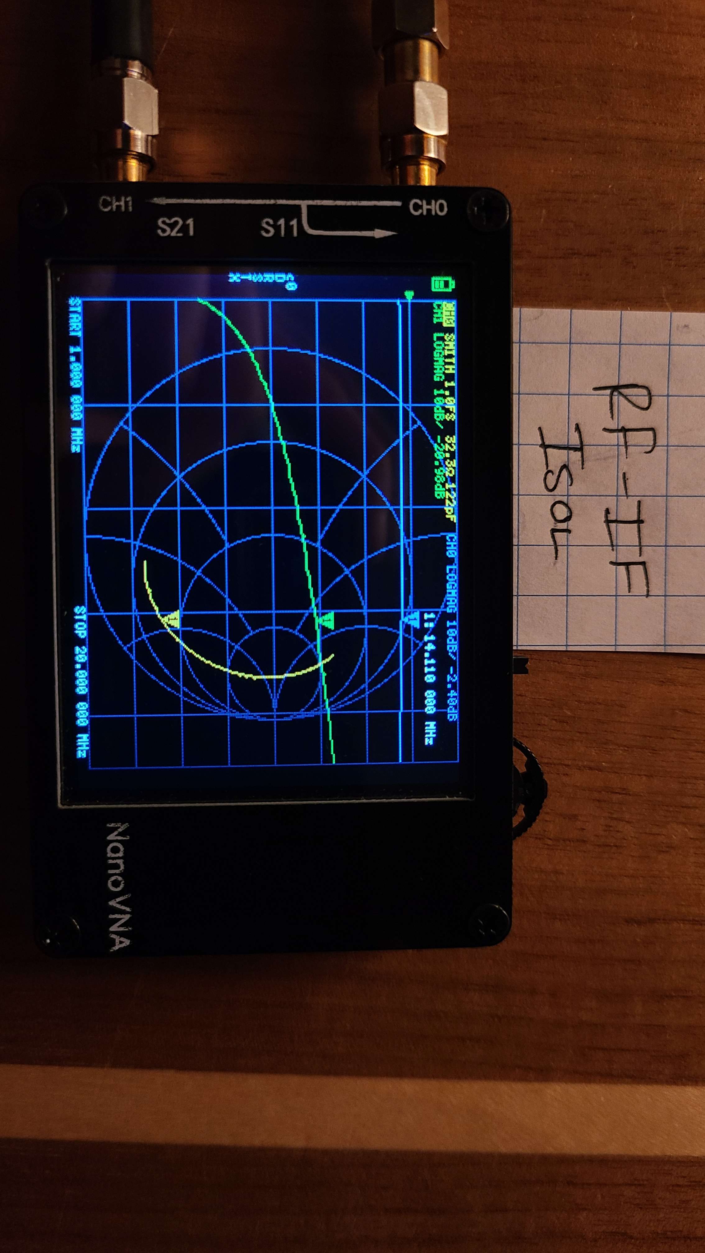
Mixer Isolation Test
Lastly, I tested the mixers isolation between the LO-RF ports, LO-IF ports, and RF-IF ports.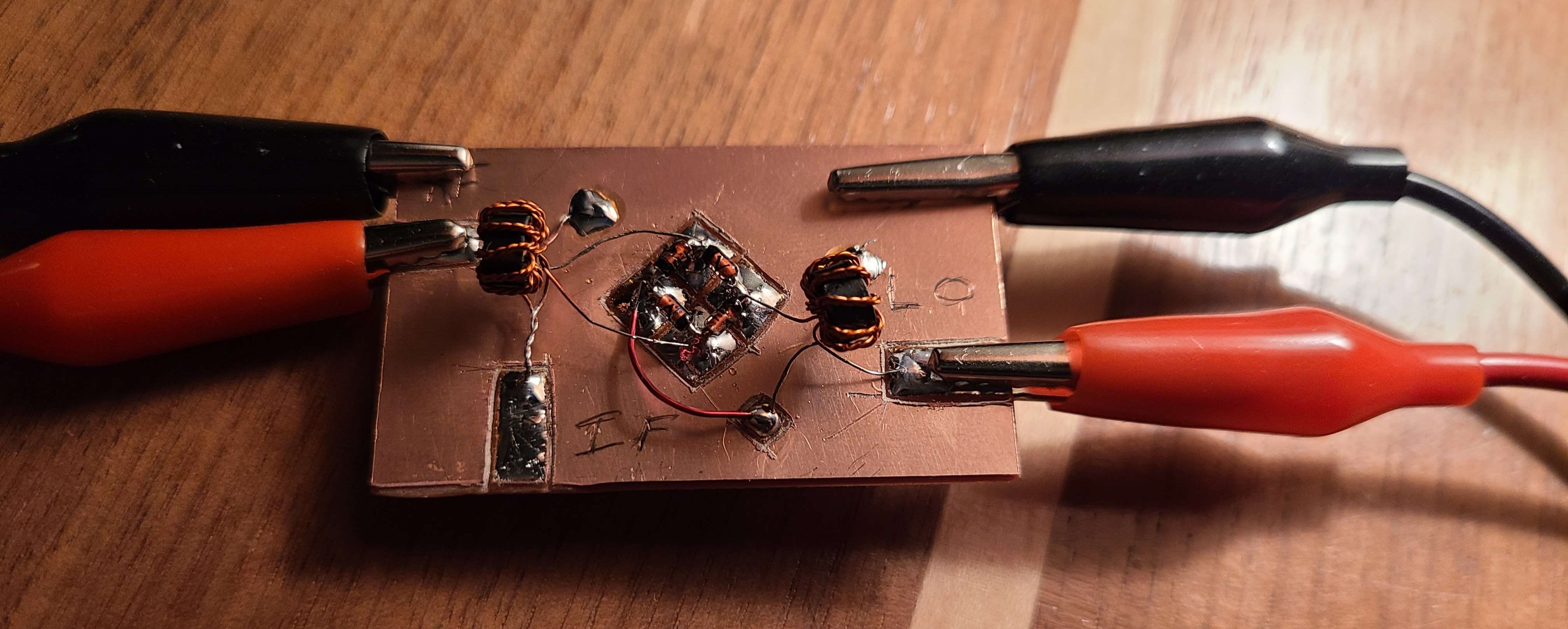
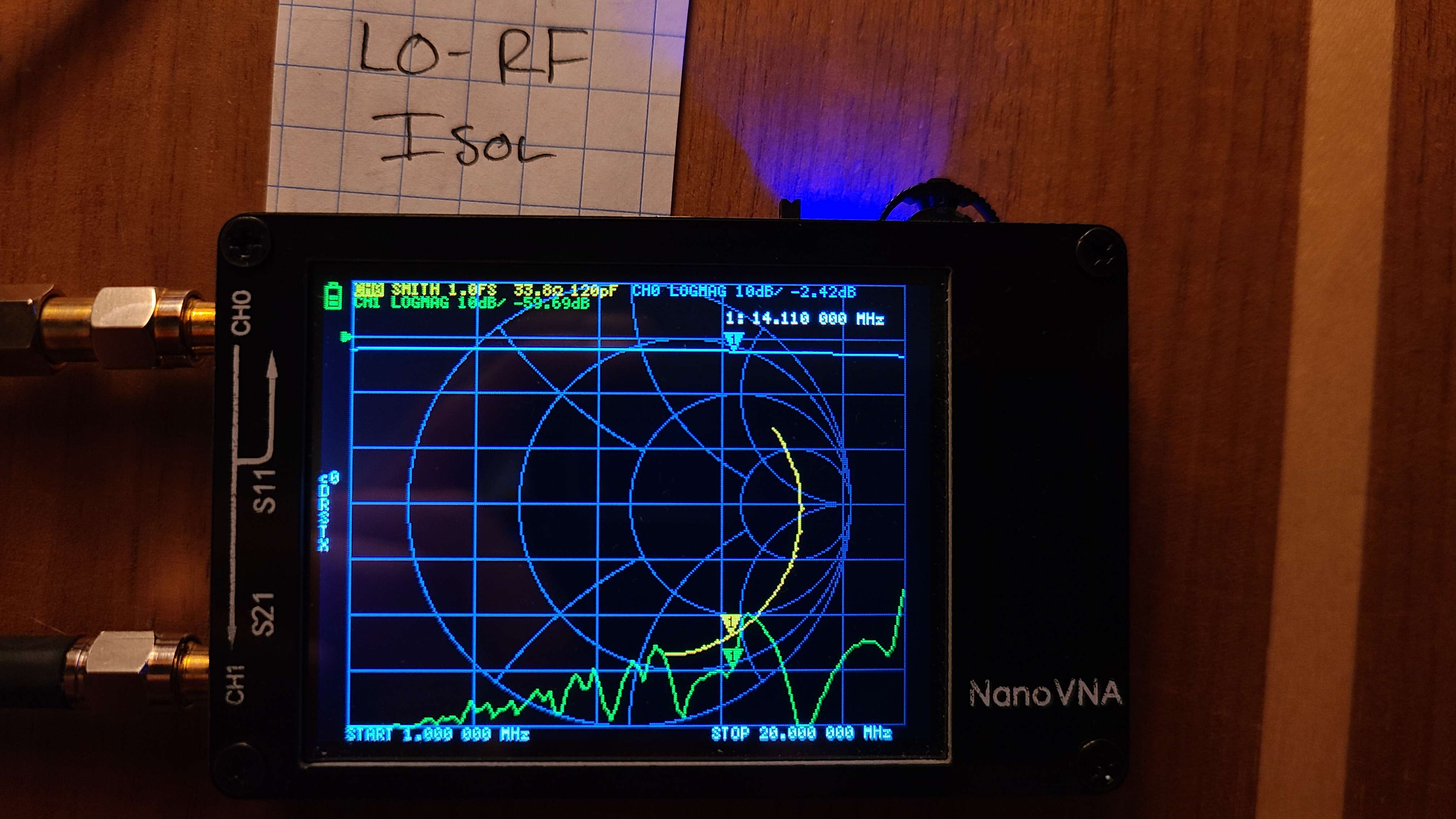
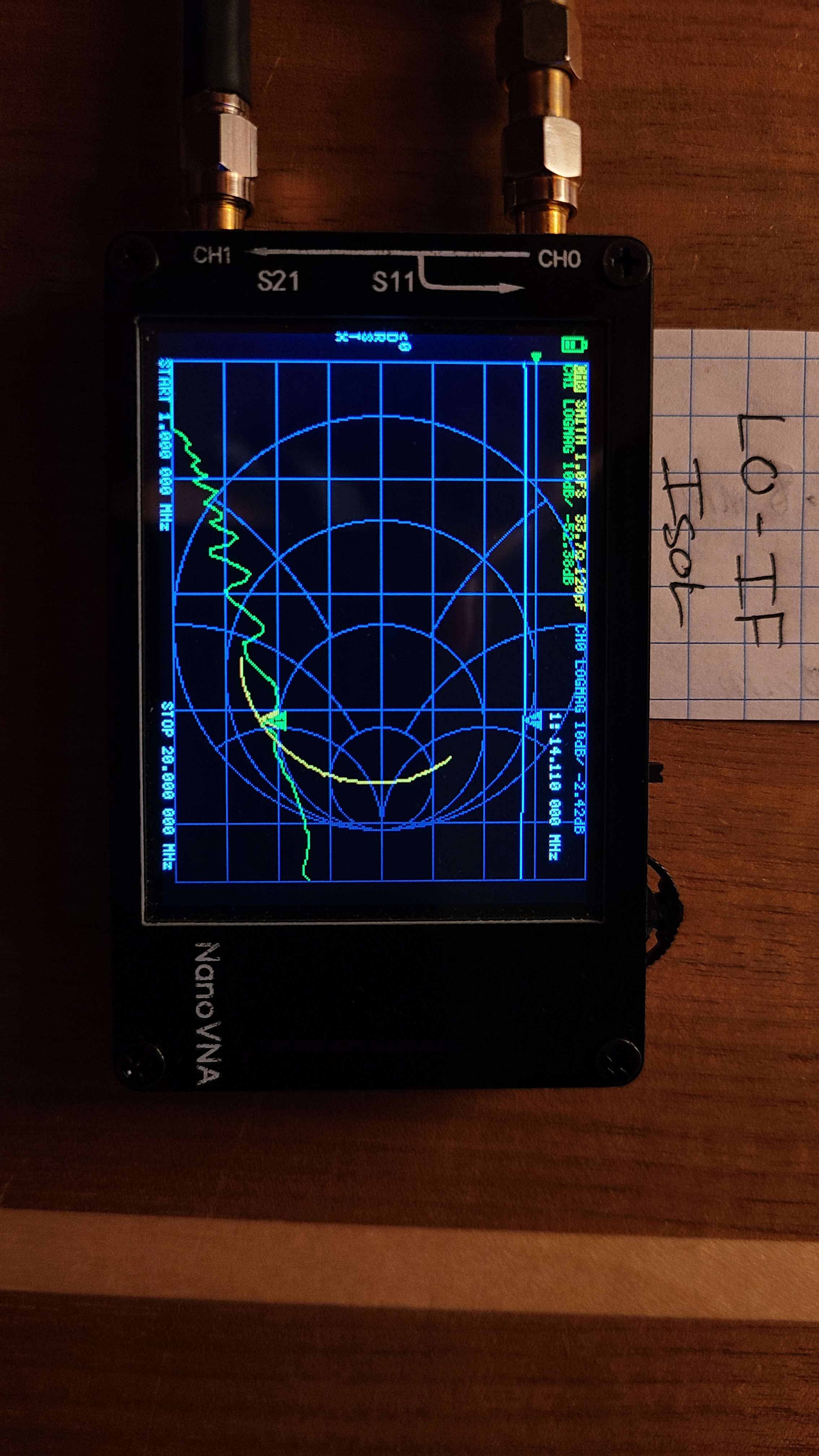
The isolation of each port ended up being:
- LO-RF Isolation: 59.7 dB
- LO-IF Isolation: 52.4 dB
- RF-IF Isolation: 21.0 dB
Remarks
Overall, the mixer design works very well, and should function with no problem in the radio. I learned a number of things in the process of designing, building, and testing this project.