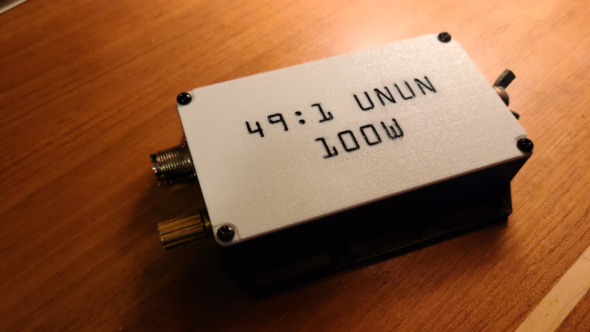
I recently purchased my first portable HF transciever, the Yeasu FT-891, and wanted to get on the air. I didn't have any antenna that I could use, so I decided to build an end-fed half wave (EFHW) antenna for the 40m band (and its harmonics, the 20m, 15m and 10m bands).
At the heart of an EFHW antenna would be its 49:1 transformer.
The Schematic
An EFHW antenna is no different from a resonant dipole other than how the feedpoint is connected. If you take a regular dipole and shift its feedpoint to the end, the antenna element is no longer current-driven, but instead voltage driven. That is, the impedance is high at the end of the element. In the case of an EFHW, the impedance we try to match to is usually 2450 Ω. This means a 49:1 impedance transformation is required to match the antenna with a 50 Ω network.
For the HF band, it is typical to use a 43-mix ferrite material for the transformer core. Being that I plan to operate at a power of 100W, I will use an FT240-43 ferrite toroid.
The number of primary and secondary turns can be determined by using an ideal transformer formula and choosing a primary turn count of 2 turns.
Using the formula $\sqrt{\frac{Z_p}{Z_s}} = \frac{N_p}{N_s}$ we know $N_p = 2$ and $\frac{Z_p}{Z_s} = 49$ so the resulting secondary turn count is $N_s = 14$.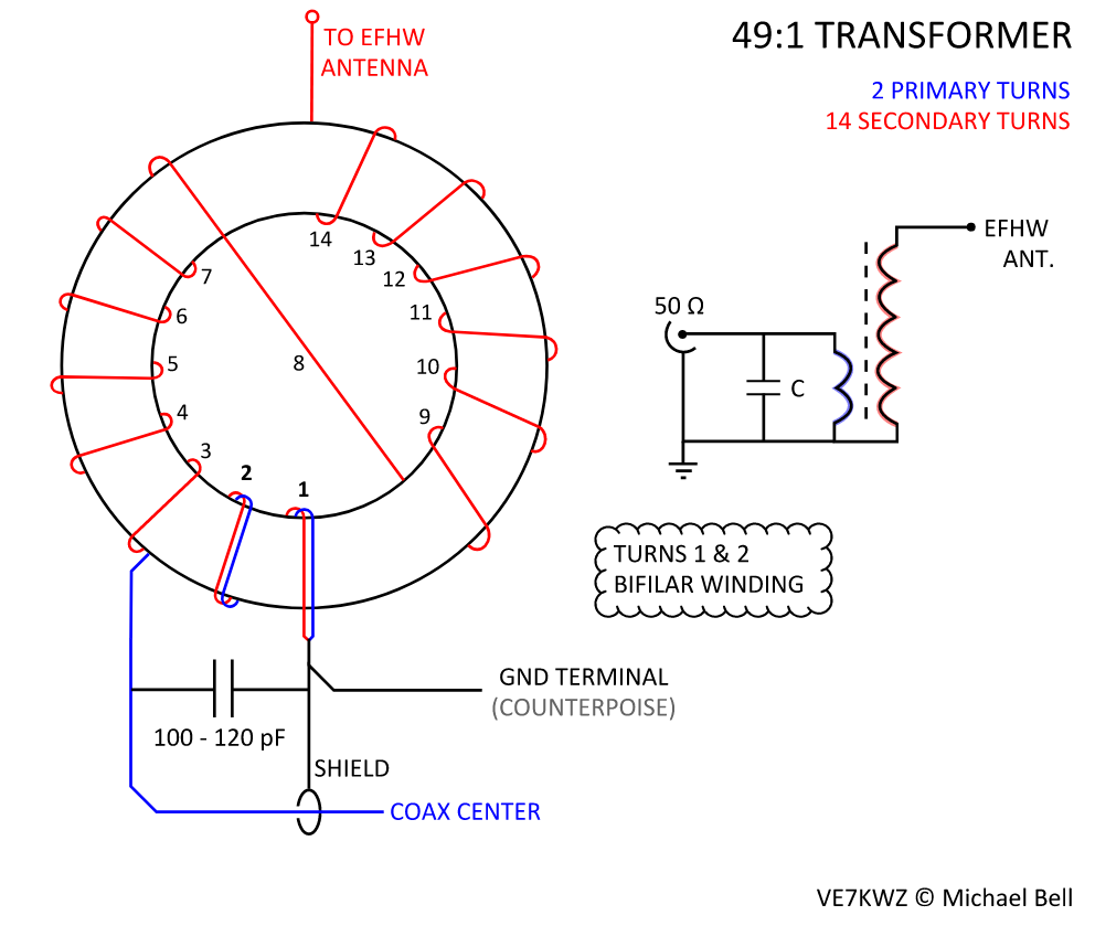
Construction of the UnUn
To build the UnUn, I repurposed the connectors from an old 4:1 BalUn I had made a few years ago.
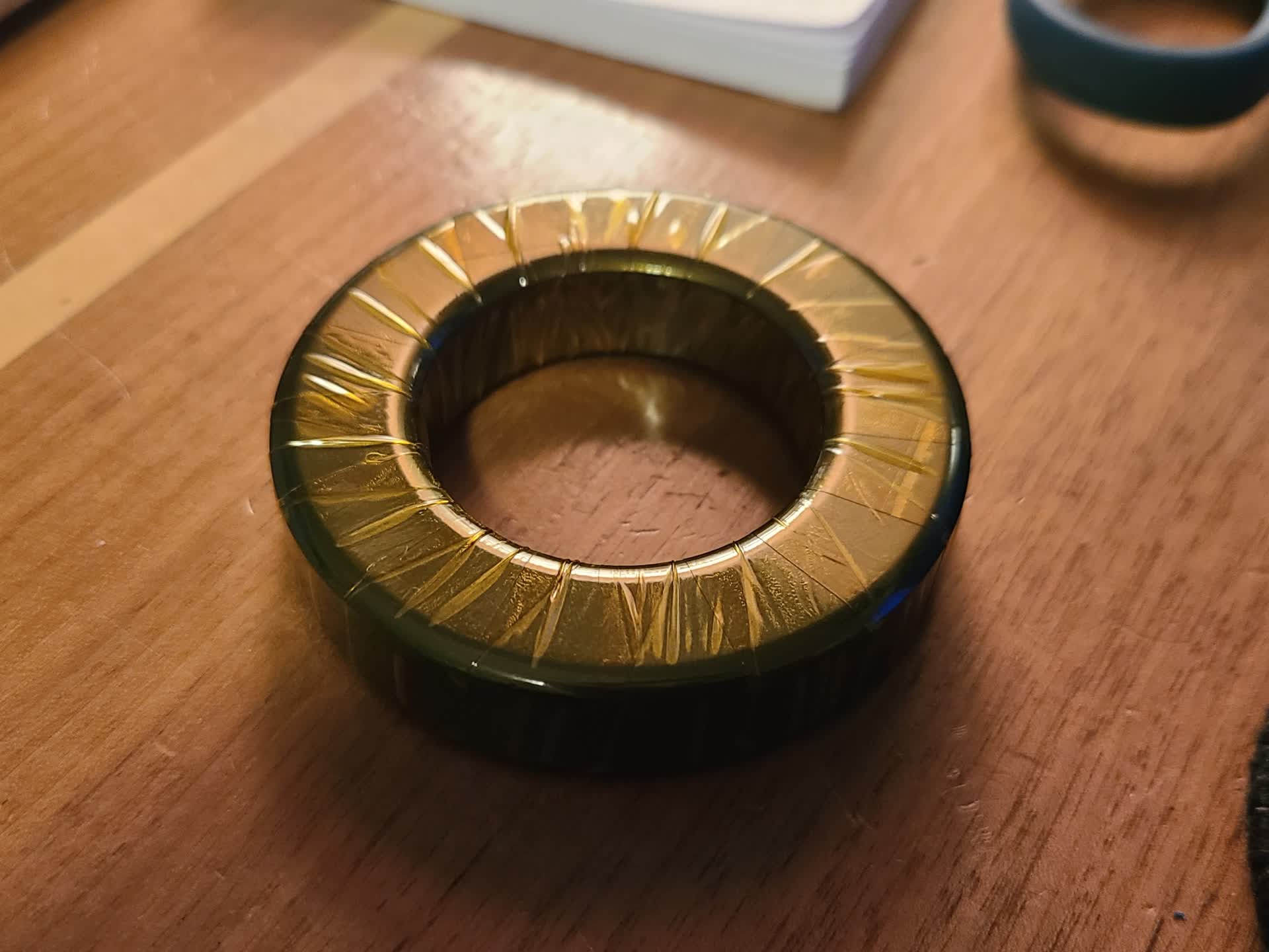
I started by wrapping the toroid with some kapton tape as an extra measure against any possible shorting. It also protects the enamel coating of the wire from scratching against the ferrite material.
The magnet wire used to wind the transformer was 18 gauge (about 1 mm diameter). This gauge should provide a low loss for HF operations.
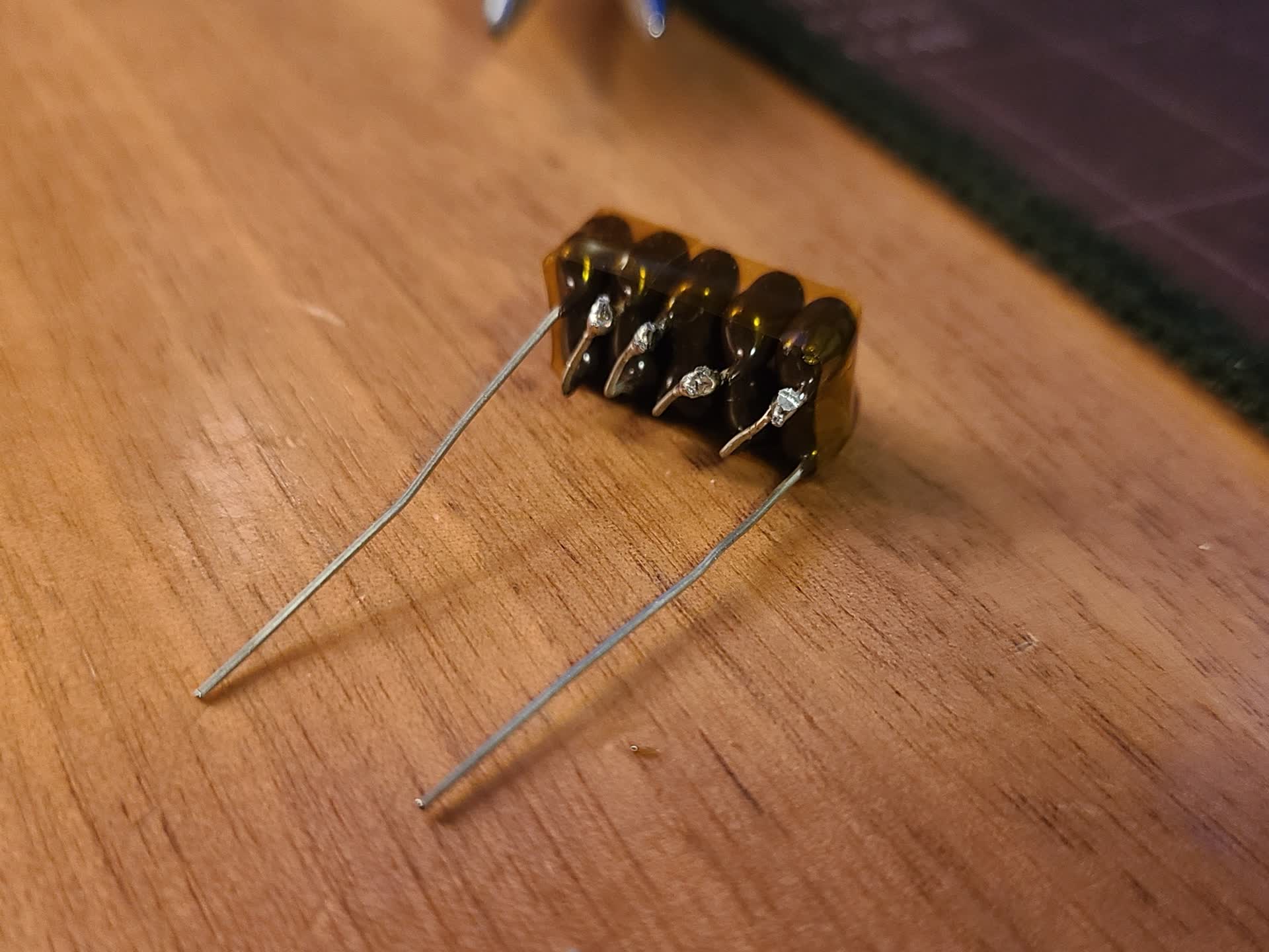
The capacitor needs to be as low loss as possible, I used some spare 500 V 560 pF Silver Mica capacitors I had available. To achieve a capacitance around 100-120 pF, I put 5 of the 560 pF capacitors in series which provides 112 pF of capacitance and a voltage rating of 2500 V. Possibly overkill for something like this.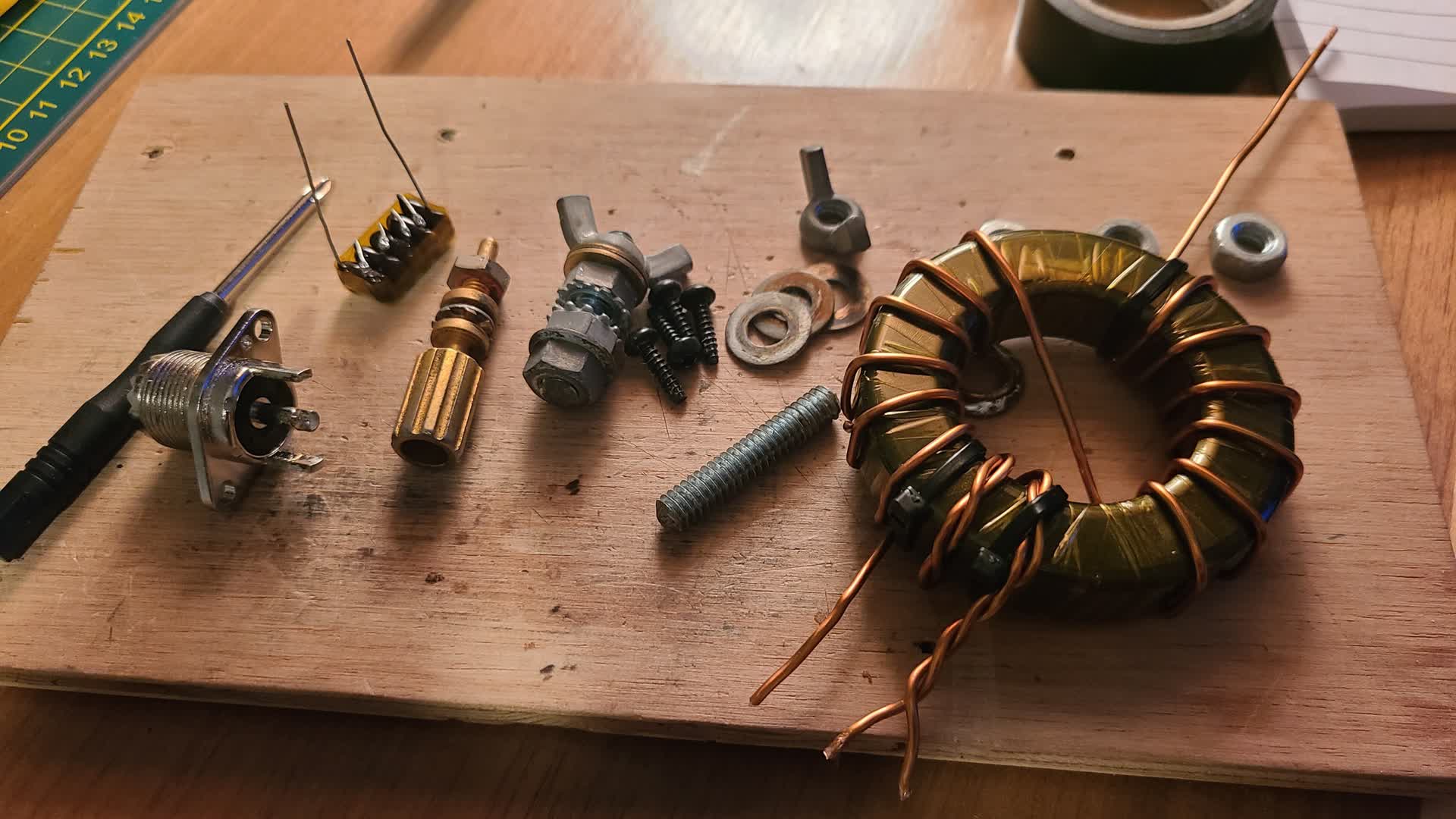
I designed and 3D printed an enclosure to hold everything together as compact as I could, leaving some space for making connections. The goal is to make this UnUn portable and slim.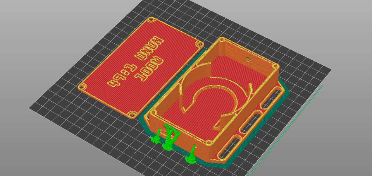
The assembled UnUn fit nicely inside the enclosure, with everything fitting very securely in place.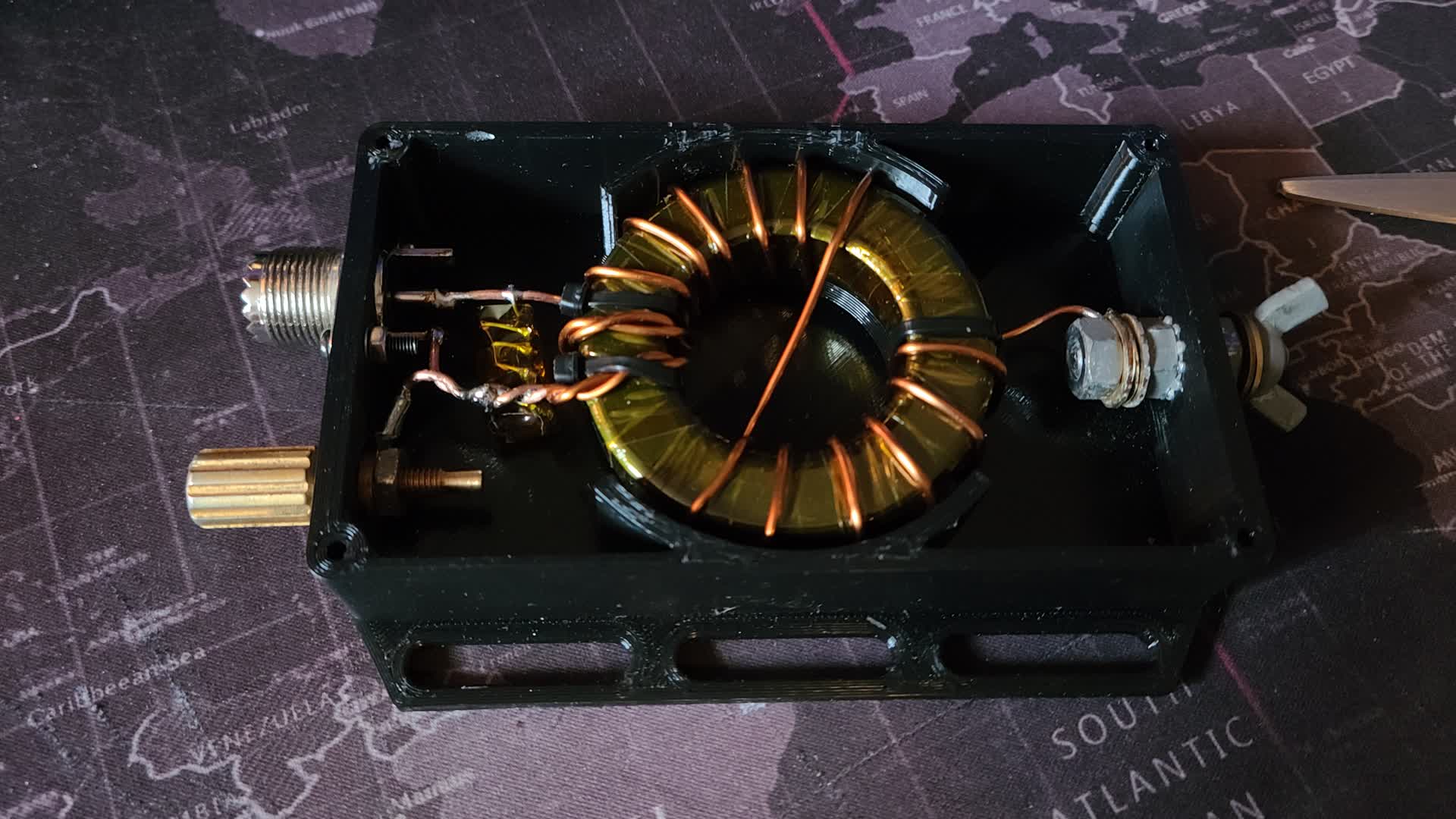
Quality Control (Testing)
Now building a 49:1 transformer is one thing, but I need to test it to ensure I have a good match across the HF frequency allocation.
To test the transformer, I took two 4.7 kΩ resistors and placed them in parallel with eachother between the antenna connection point and the counterpoise connection point. This should present a 2350 Ω impedance at the antenna side, which is close to the ideal 2450 Ω.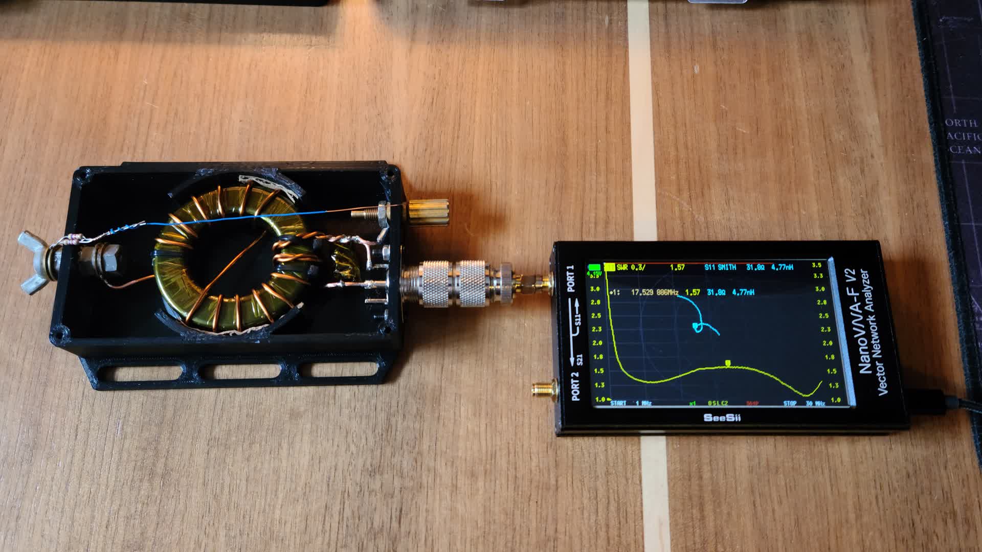
Then I measured the impedance and VSWR using my NanoVNA-F. If it were perfect, the reading would show 2350/49 = 47.96 Ω but of course nothing is perfect. However, the current results are very good for this transformer!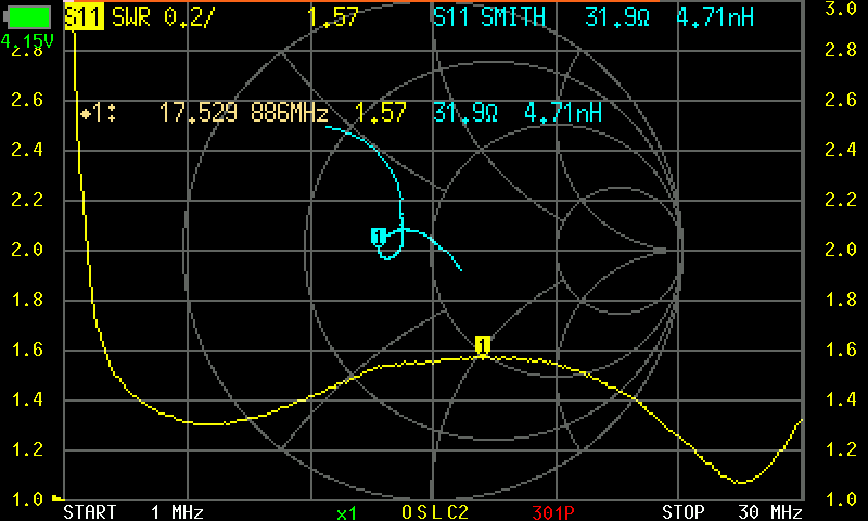
Enclosed Box
The result.