Lately I have been chipping away at the idea of creating a superheterodyne reciever (and potentially tranciever). One of the key blocks within the design of a superheterodyne reciever is a mixer. I have a number of options when it comes to mixer topologies, and among them I wanted to give the gilbert cell a look.
Gilbert Cell Experiments
Simulation
The design of a gilbert cell consists of three differential amplifiers, with the first two diff. amps tail currents feeding into the third diff. amp.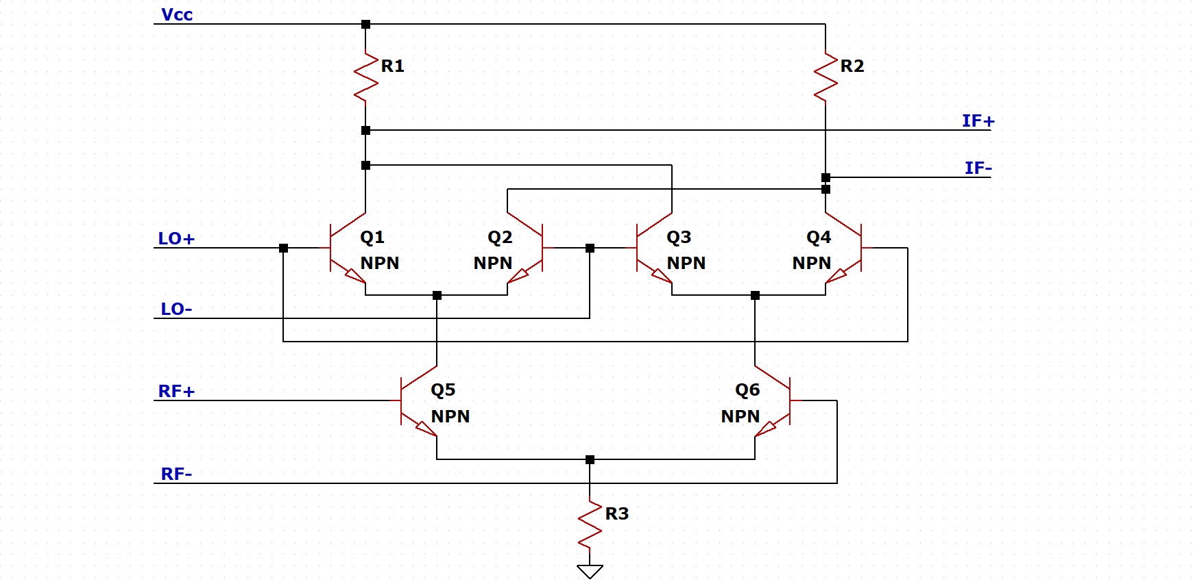
I then added some biasing resistors following a design by another engineer, and tweaking the values until the desired result was achieved. Additionally a 1:1 balun was placed at the IF output to convert the differential signal into single-ended.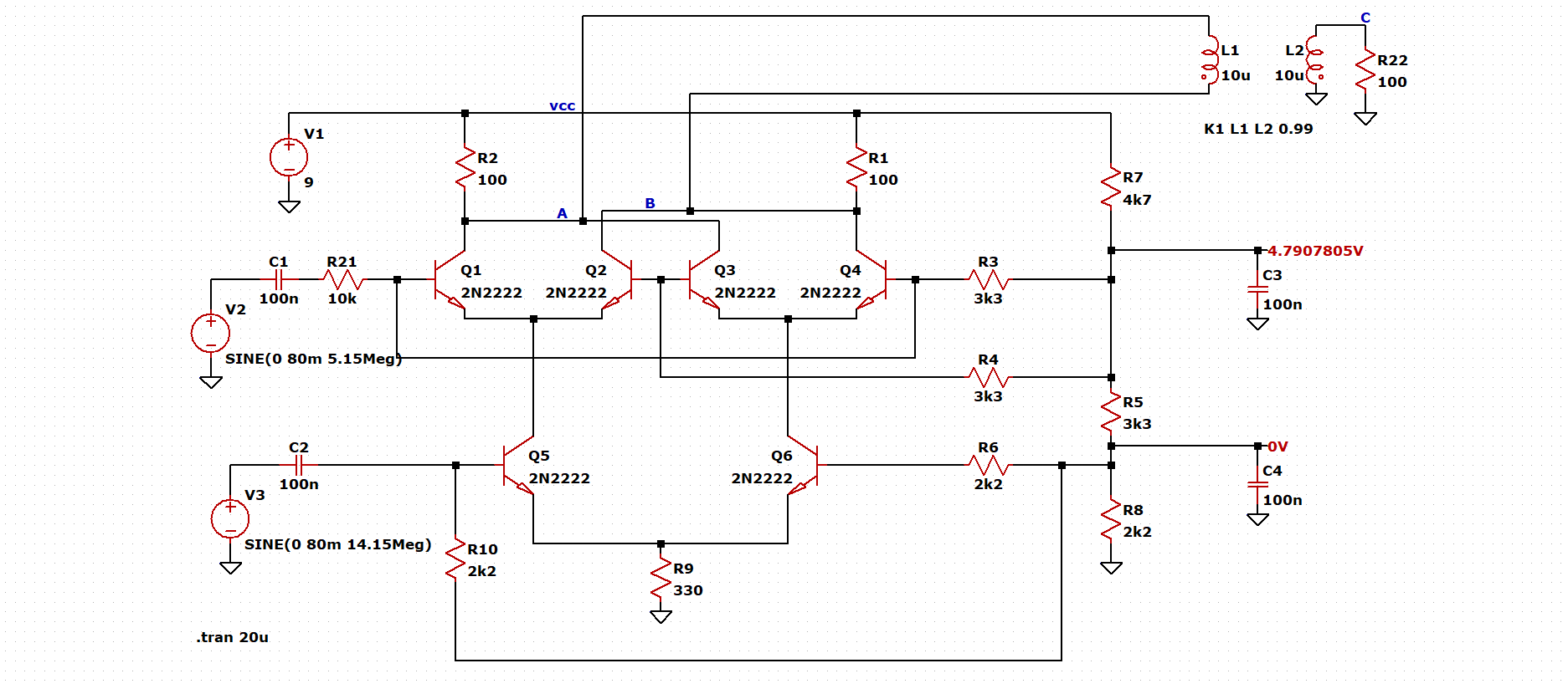
I have chosen to use 14.15 MHz as the RF input frequency, and 5.15 MHz as the LO input frequency. Being that mixers output the sum and difference of the RF and LO frequencies, this simulation should produce a sine wave at 9 MHz and 19.30 MHz.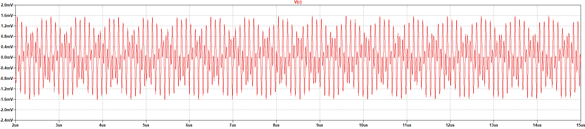
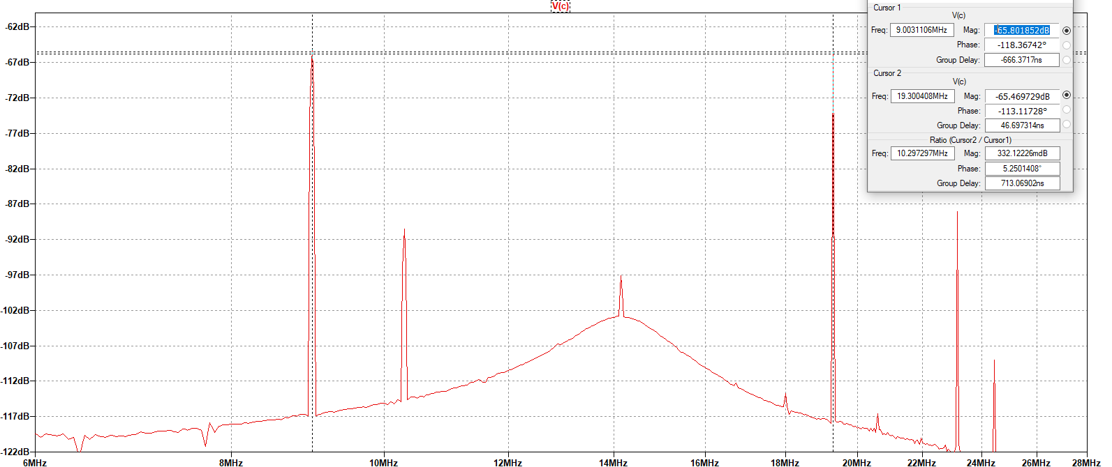
The result of the simulation shows a clean signal of both 9 MHz and 19.3 MHz sine waves. Due to the magnitude of the LO input, the output shows some of the LO signal on the output, which is known as LO leakage.
Prototype
I started prototyping the gilbert cell on a solderless breadboard. This makes building it easy and simple, but limits me on the frequency range which I can test the circuit. I test the circuit at various frequencies between 1 kHz and 100 kHz. Being that I am workin within this frequency range (and the fact that I didn't have any suitable ferrite toroids for a balun on hand), I used an operational amplifier as a differential to single-ended converter.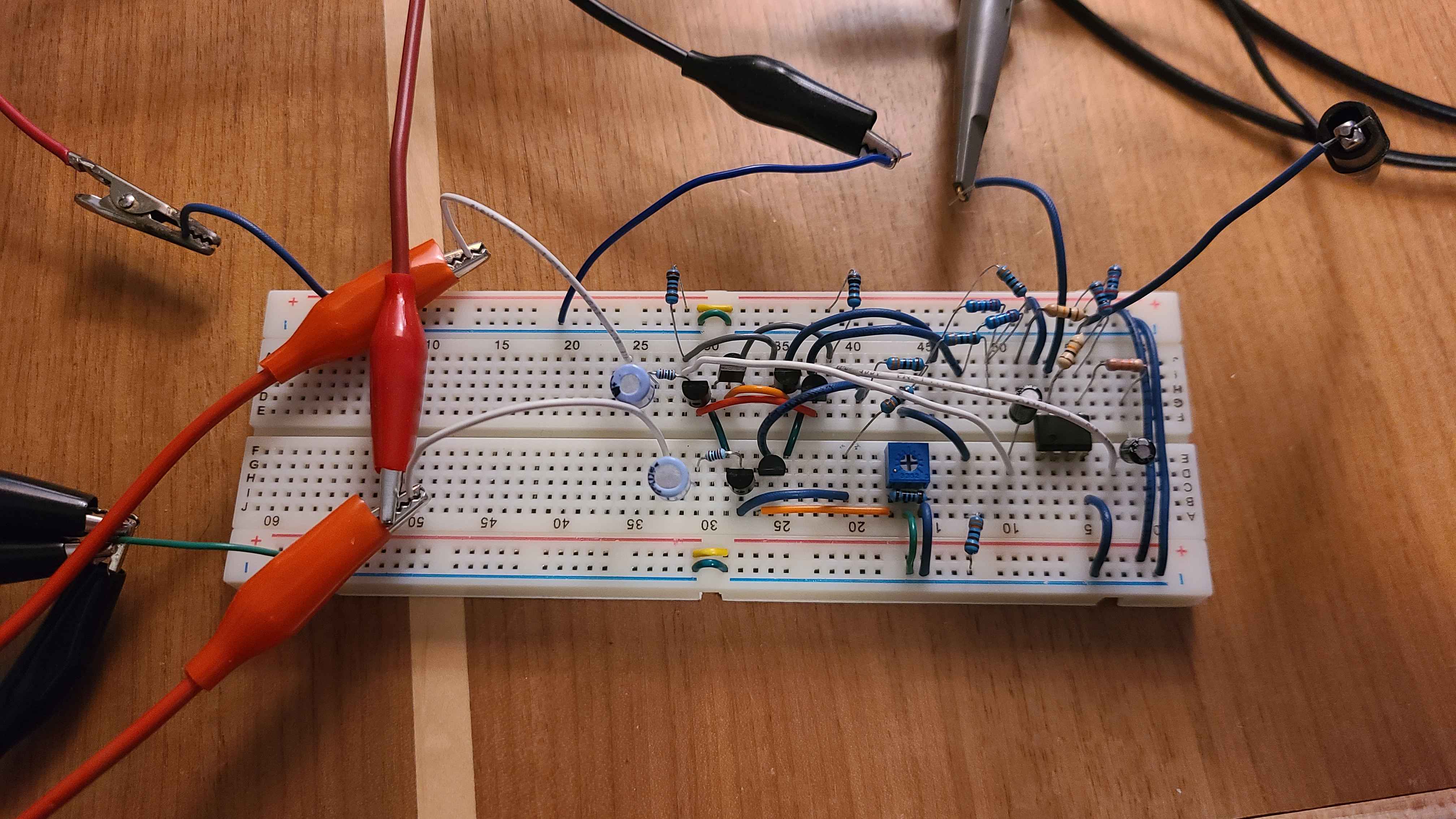
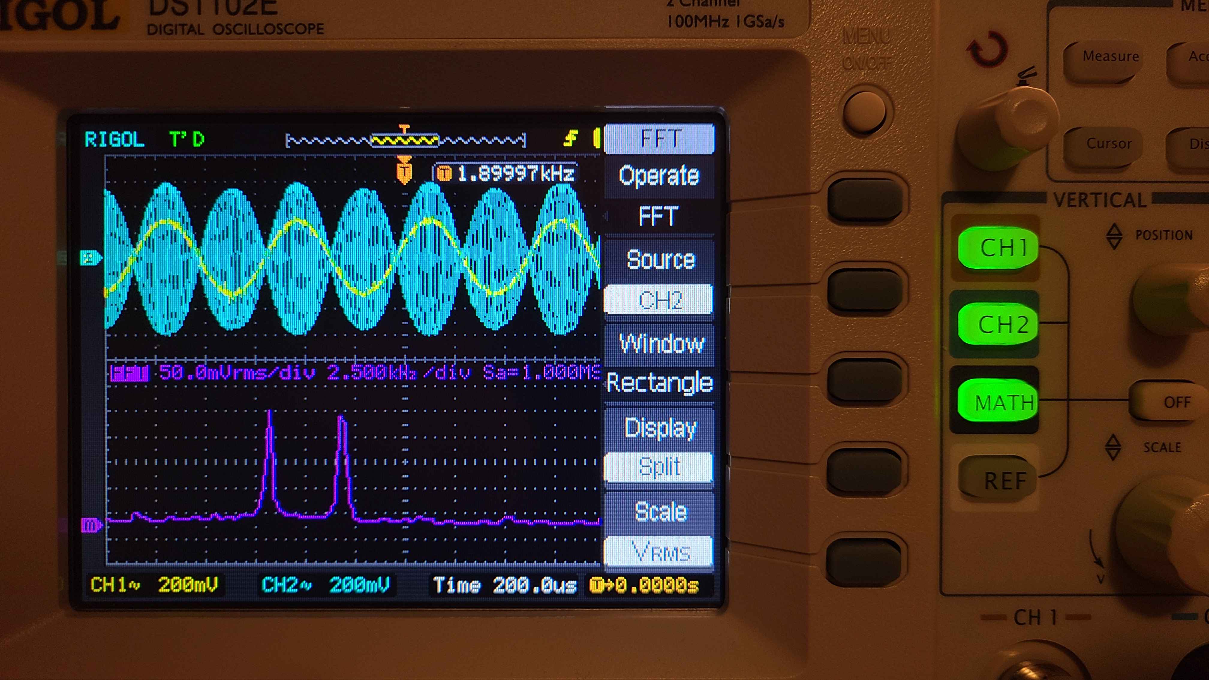
The results of the tests were successful. I was able to create the sum and difference of two input frequencies.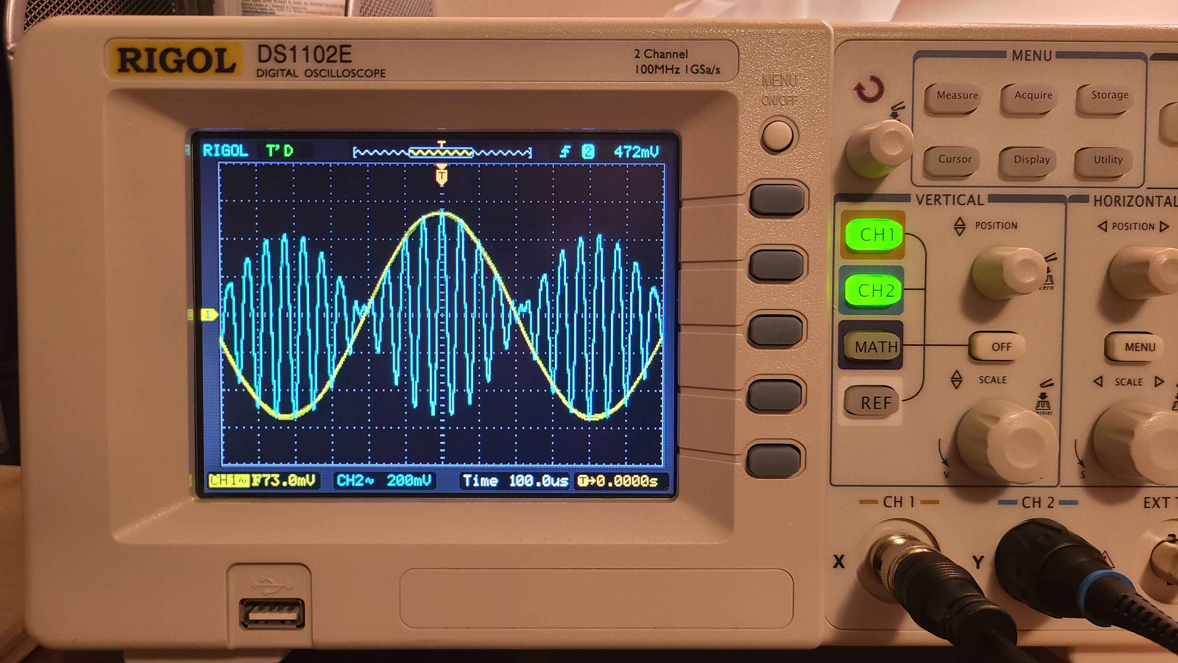
Using an input of 10 kHz and 1.9 kHz, I created what is essentially a double sideband supressed carrier (DSB-SC) signal centered at 10 kHz.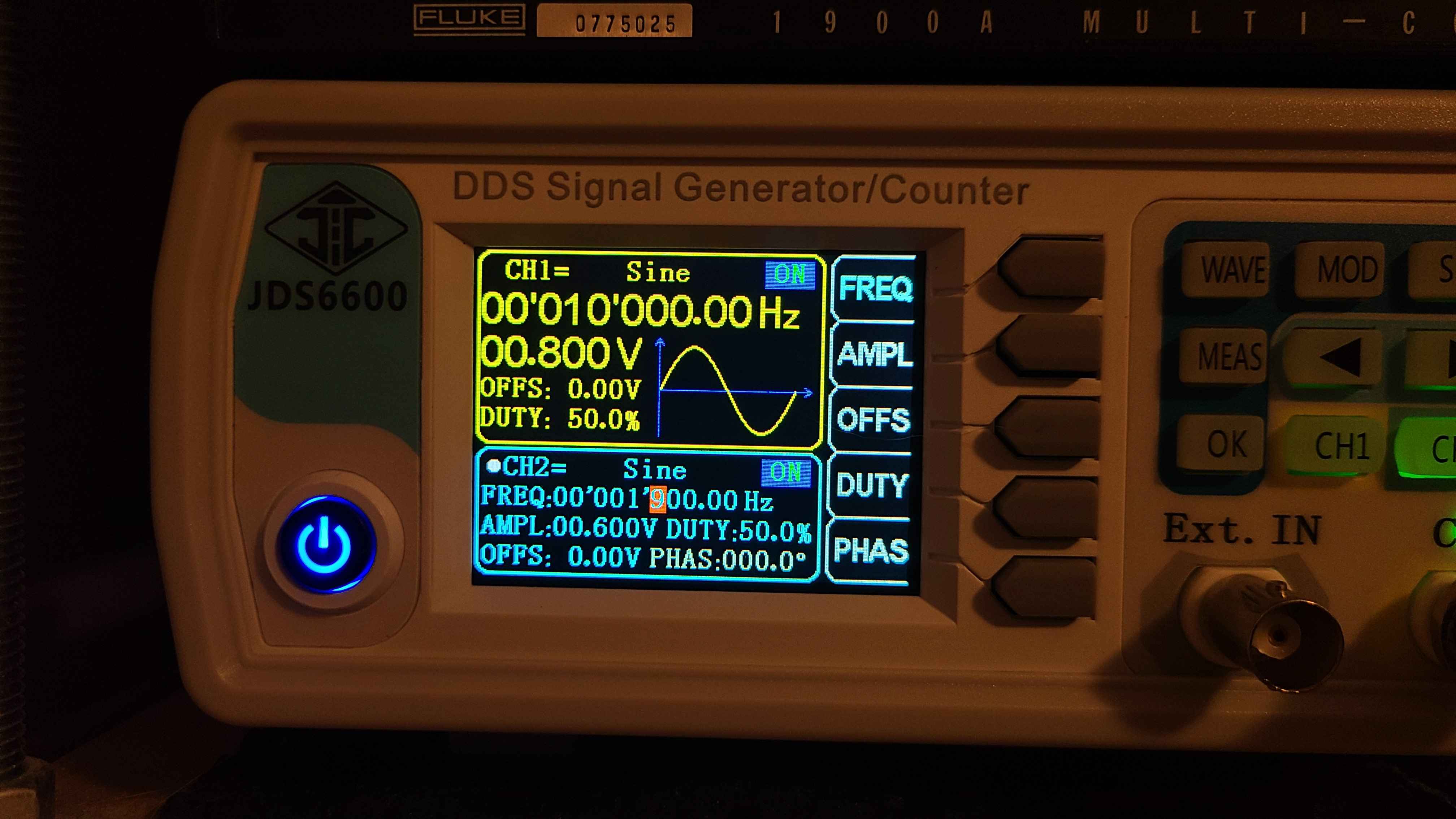
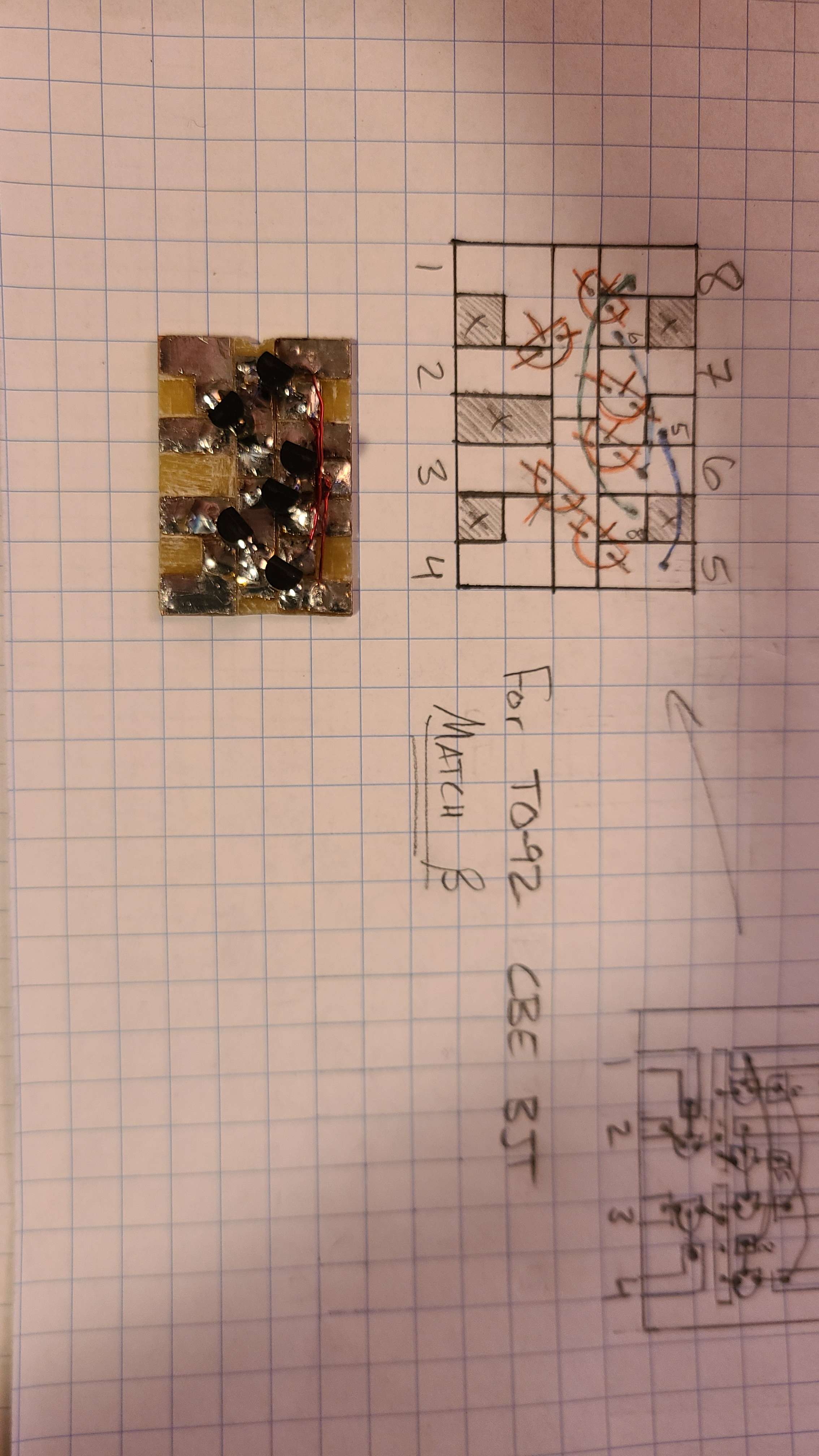
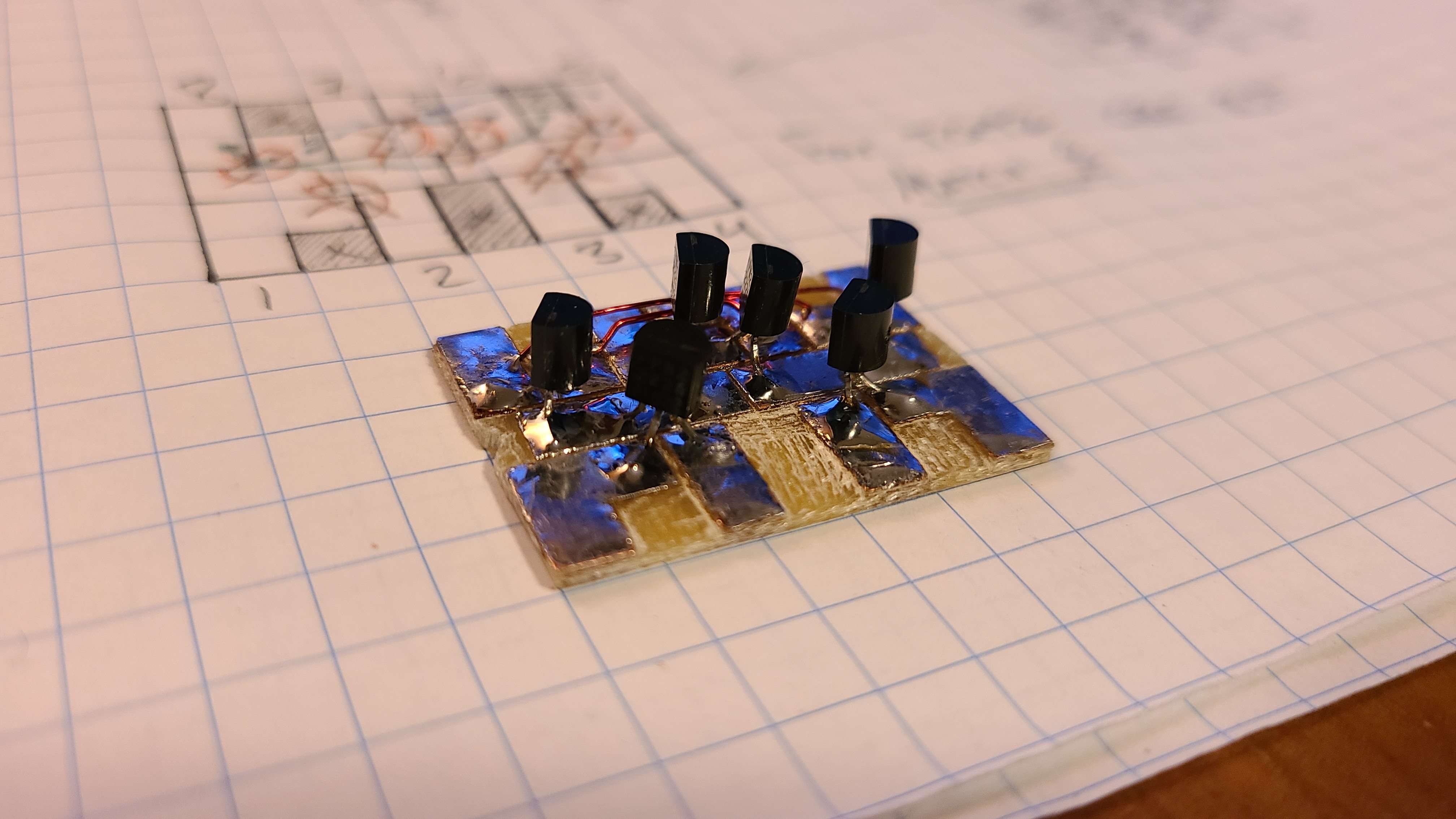
What's to come...
Later on I built the gilbert cell (without the biasing components) on a piece of copper clad board for later experimentation. I am still not sure whether to use a discrete gilbert cell as shown above, or to order some ferrite cores and create a double balanced diode ring mixer. For now, they are both options on the table.