Among my radio equipment, the one tool I didn't have was a 50 Ω dummy load. Using a 250W rated RF resistor, I created a dummy load with a wattmeter made from an old VU galvonometer.
Construction
The RF resistor I used was an RFP250N50 resistor rated at 250W 50 Ω. The resistor on its own is not capable of dissipating 250W of heat passively, so it required a heatsink. Using an older aluminum heatsink I had lying around, I cored it out in the middle and mounted the resistor inside with a SO239 connector on the rear.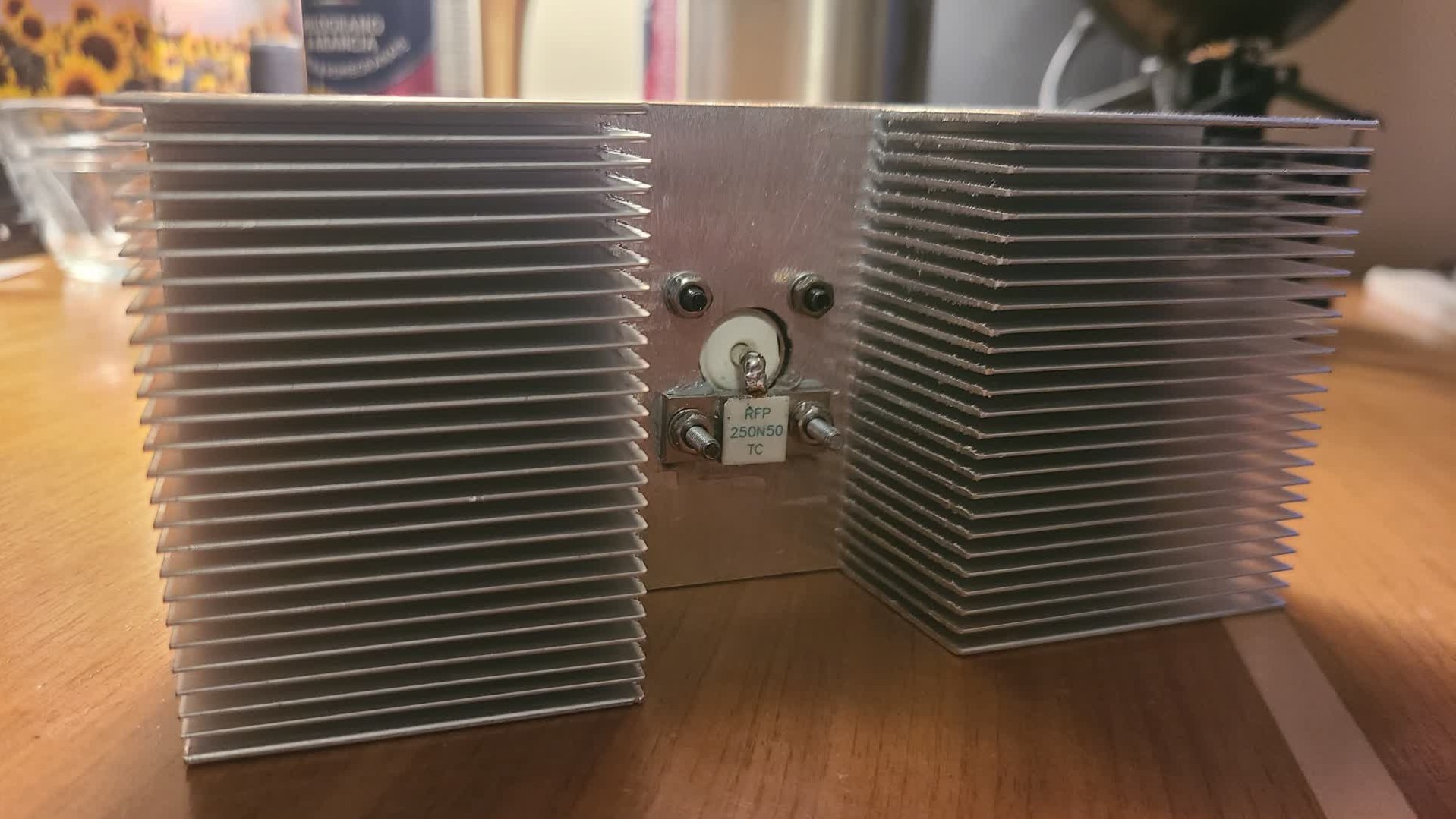
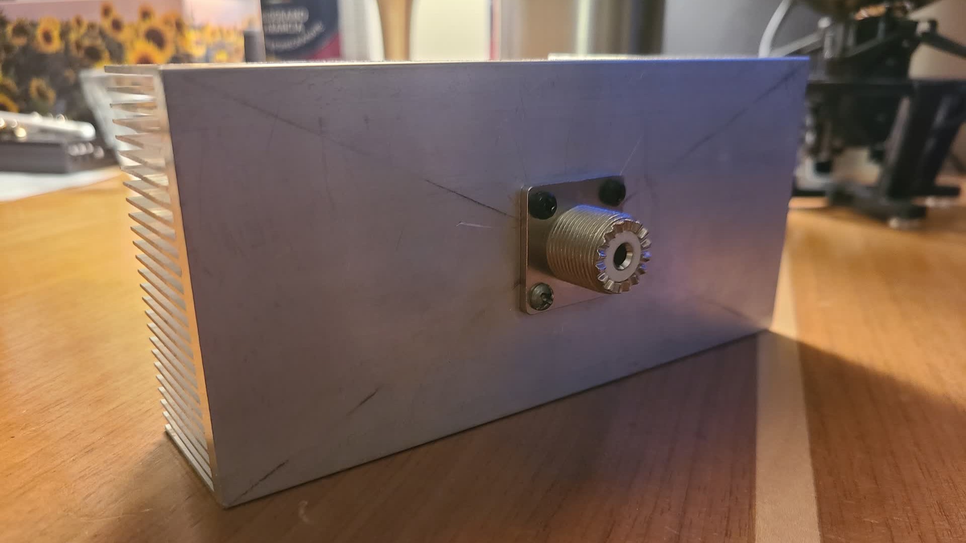
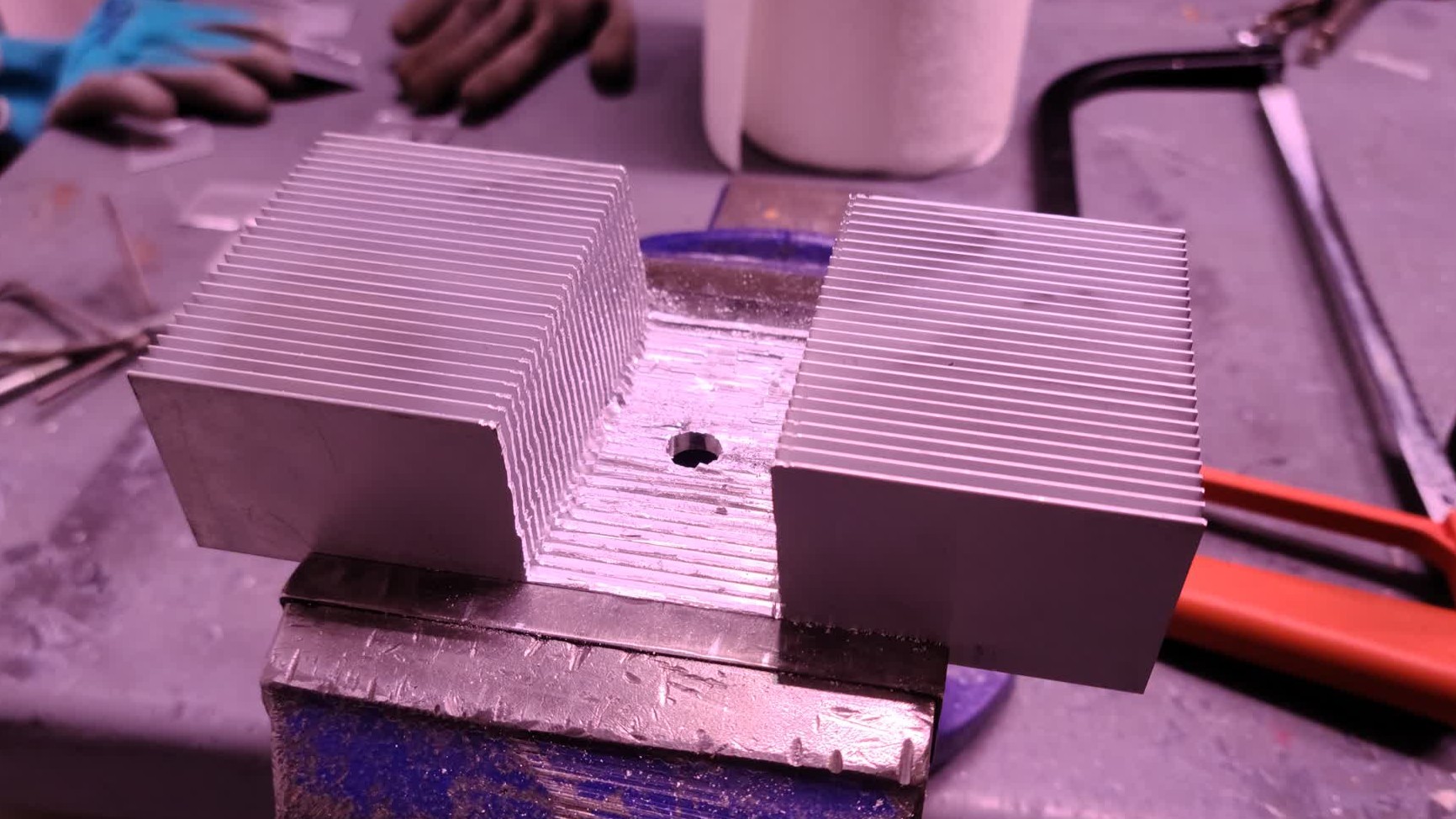
To help with thermal conductivity, some off the shelf PC CPU thermal paste was used between the heatsink and resistor.
I did a quick S11 measurement using my NanoVNA. The result was fairly good, with the impedance being almost purely real at 50 Ω in the HF band, and the higher VHF range turning slightly more capacitive. This could be due to the capacitance of the BAV99 diodes used in the next step.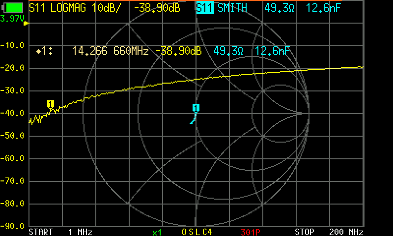
Wattmeter
The addition of a wattmeter complicates the project slightly, but adds much more use to a dummy load. So I didn't need to change any batteries, I opted to use a fully passive method of displaying power. This was done using a galvanometer I salvaged from some old audio equipment.
The schematic of the wattmeter is shown: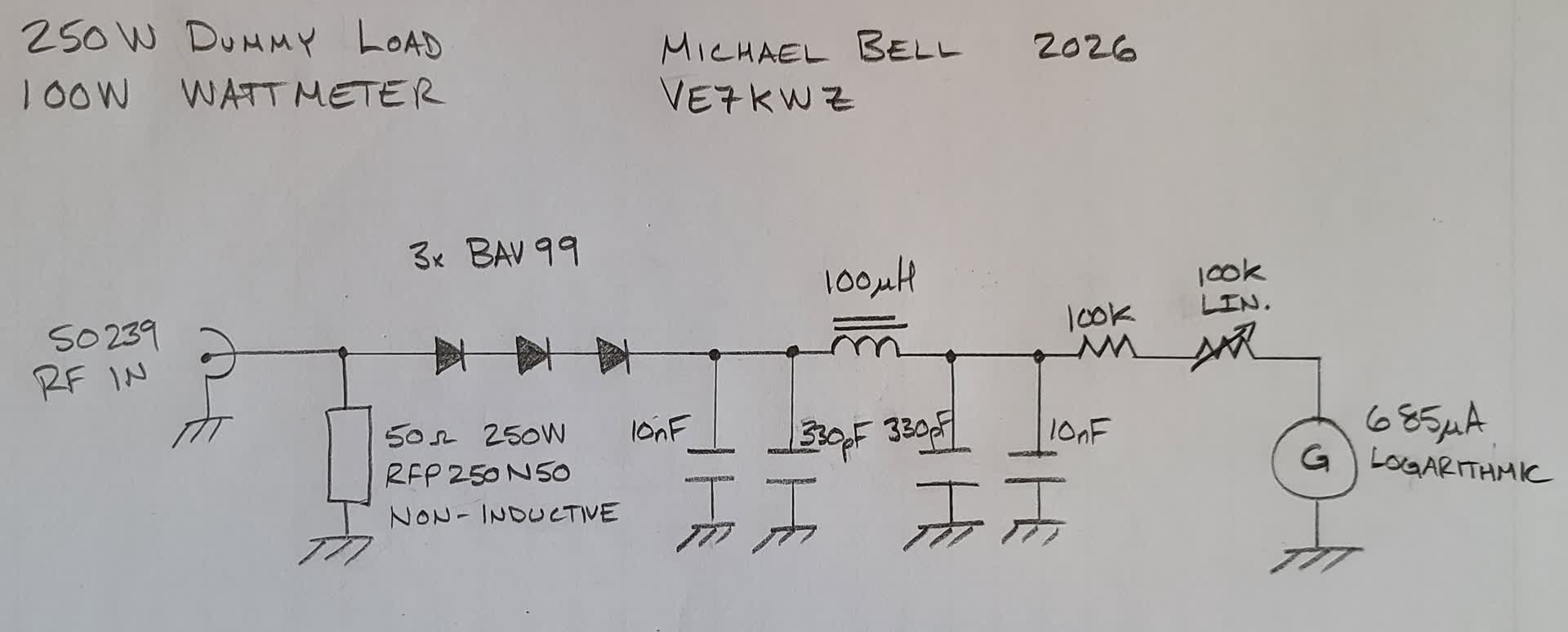
The 3 diodes in series are BAV99's which are general purpose switching diodes in an SOT-23 package. The reason I used 3 was to overcome the peak reverse voltage rating. Each diode has a rating of 75 V, so using 3 allows the wattmeter to handle 225 V. At 250 W of RF, the peak voltage the diodes will experience should be 158 V which falls well within the 225 V maximum.
Bacause the Galvonometer I used was from an old audio VU meter, it has a logarithmic scale. This is both a blessing and a curse for this project. The perk of having a logarithmic power meter is that I can view a wider range of lower powers, but I have to measure the current needed to move the needle along the range of the galvo.
I set up a quick bench test using a voltage source, potentiometer, and ammeter. I then plotted the measured values and fit a curve to them.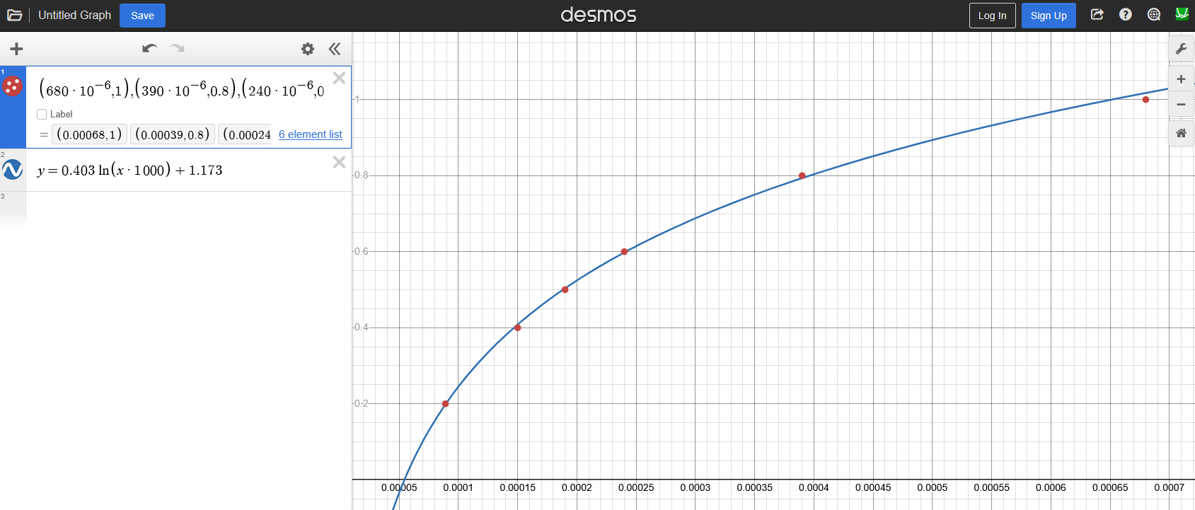
Using the generated curve I created a simple faceplate for the galvanometer.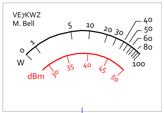
Testing and Use
Using my FT-891 HF transciever, I tested the wattmeters accuracy.