To optimize signal integrity and internal reflections within the HF superheterodyne receiver I am designing, I need to address mixing products. I tend to do this through the use of diplexers.
In an RF receiver, the mixer is a frequency-translation building block that operates non-linearly. A consequence of this non-linear behavior is the generation of numerous unwanted mixing products, such as harmonics and intermodulation spurs, alongside the desired signal. Depending on the termination or impedance matching, these undesired products are either absorbed or reflected by the devices connected to the mixer's ports. When reflected products re-enter the mixer, they undergo secondary frequency translation, creating additional spurious signals. This recursive cycle can drastically increase the spur density, potentially degrading overall system performance.
To mitigate or eliminate this recursive cycle, a diplexer can be integrated at the mixer ports. The diplexer functions by presenting a constant impedance termination across a wide bandwidth, effectively neutralizing the impedance mismatches that cause reflections. It operates by passing the desired frequency range to the next stage with minimal insertion loss, while simultaneously routing the undesired out-of-band frequencies into a matched termination load where they are safely dissipated as heat.
Diplexer Simulation
To design the diplexer, I began by designing two complementary filters, a band-pass filter and a band-stop filter. The band-pass filter transmits the desired frequency range with minimal attenuation. Meanwhile, the band-stop filter routes the unwanted out-of-band frequencies into a termination load to be safely dissipated as heat, which maintains a constant input impedance across the system.
A reliable rule of thumb I found is to design the band-pass filter with a Q factor that is at least twice that of the band-stop filter. For the circuit topology below, this means the parallel tank circuit's Q factor must be at least double the series tank circuit's Q factor: $Q_p \geq 2Q_s$.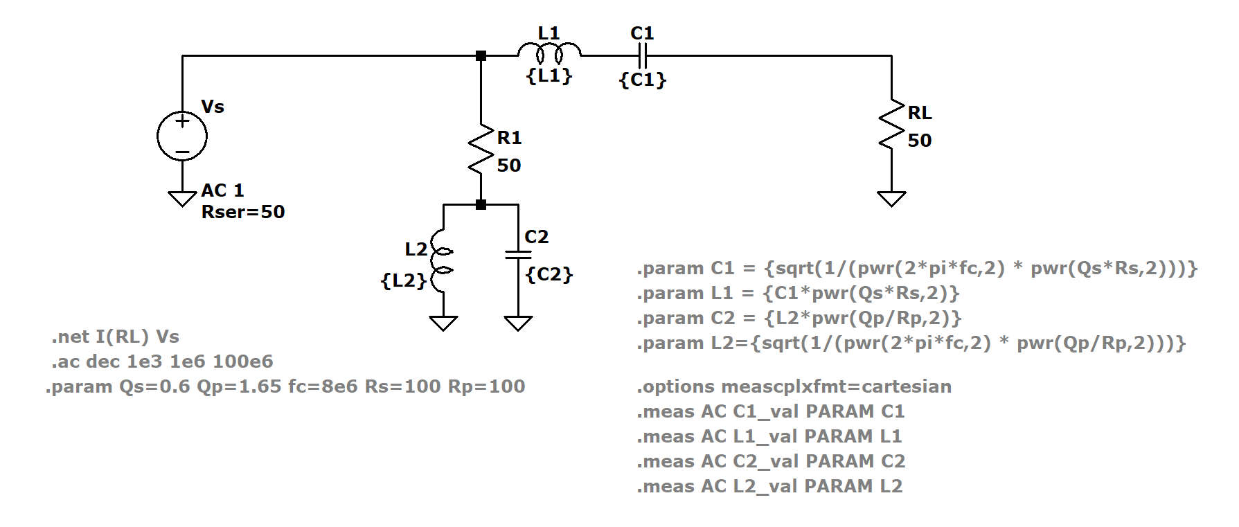
Calculating Values
Because my superheterodyne receiver utilizes an 8 MHz intermediate frequency, I want to isolate the 8 MHz IF signal produced by the mixer.
A resource I used during the creation of this diplexer was the Marki Microwave LC filter design tool. Within the filter design tool is the option to create a bandpass diplexer.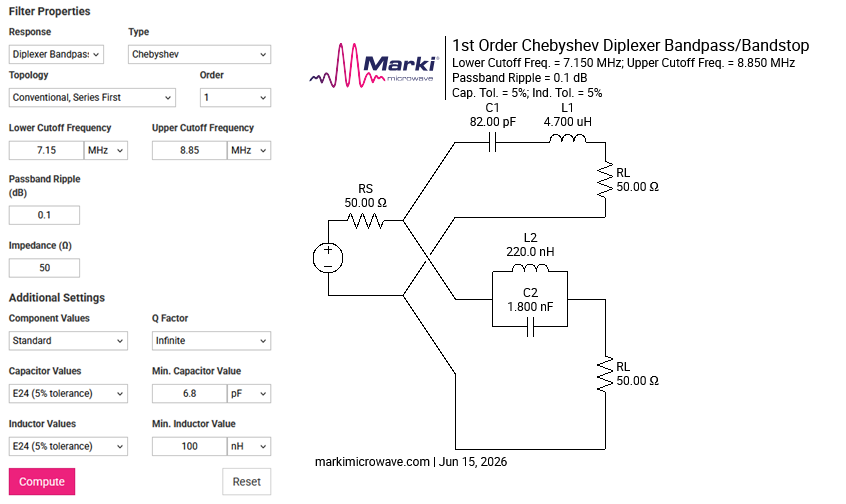
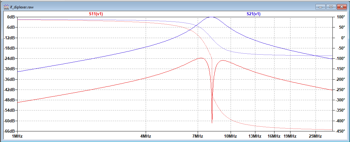
Using the series tanks values, I adjusted the parallel tanks values slightly to utilize parts I already have on hand. With the slight change I ran a simulation in LTspice.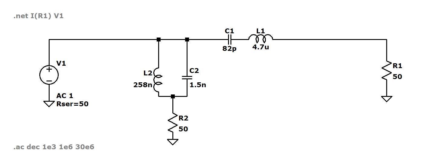
Physical Realization
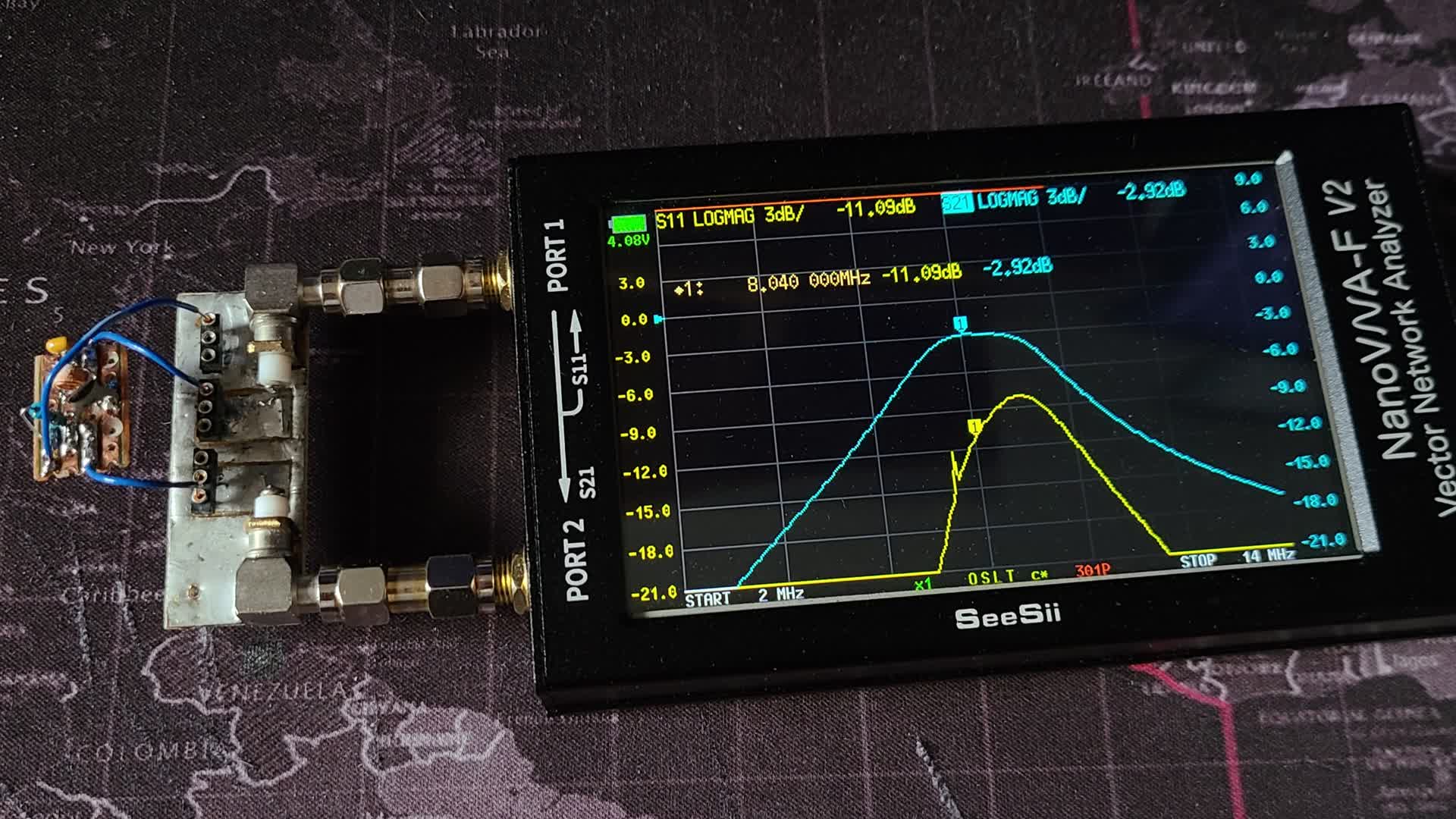
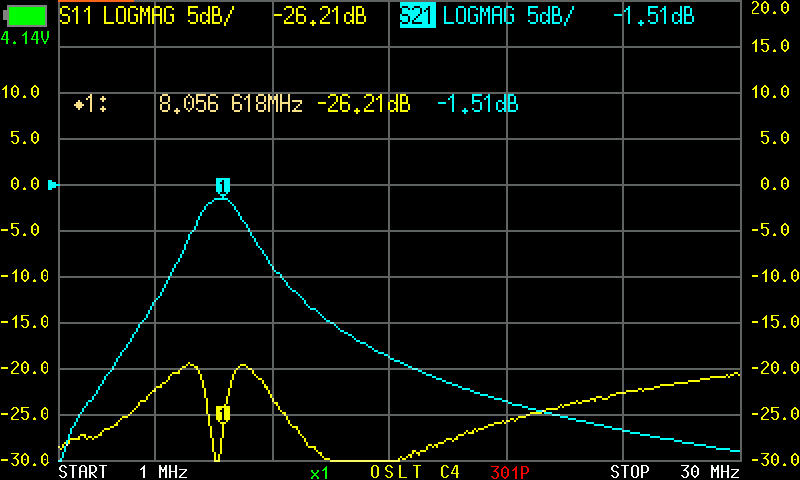
Using parts on hand, I built the diplexer on a section of strip-board and tested its response using my NanoVNA-F V2. The NanoVNA was calibrated using the test fixture to eliminate the effects of the fixture itself.
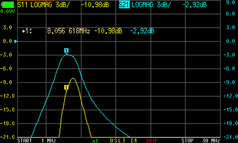
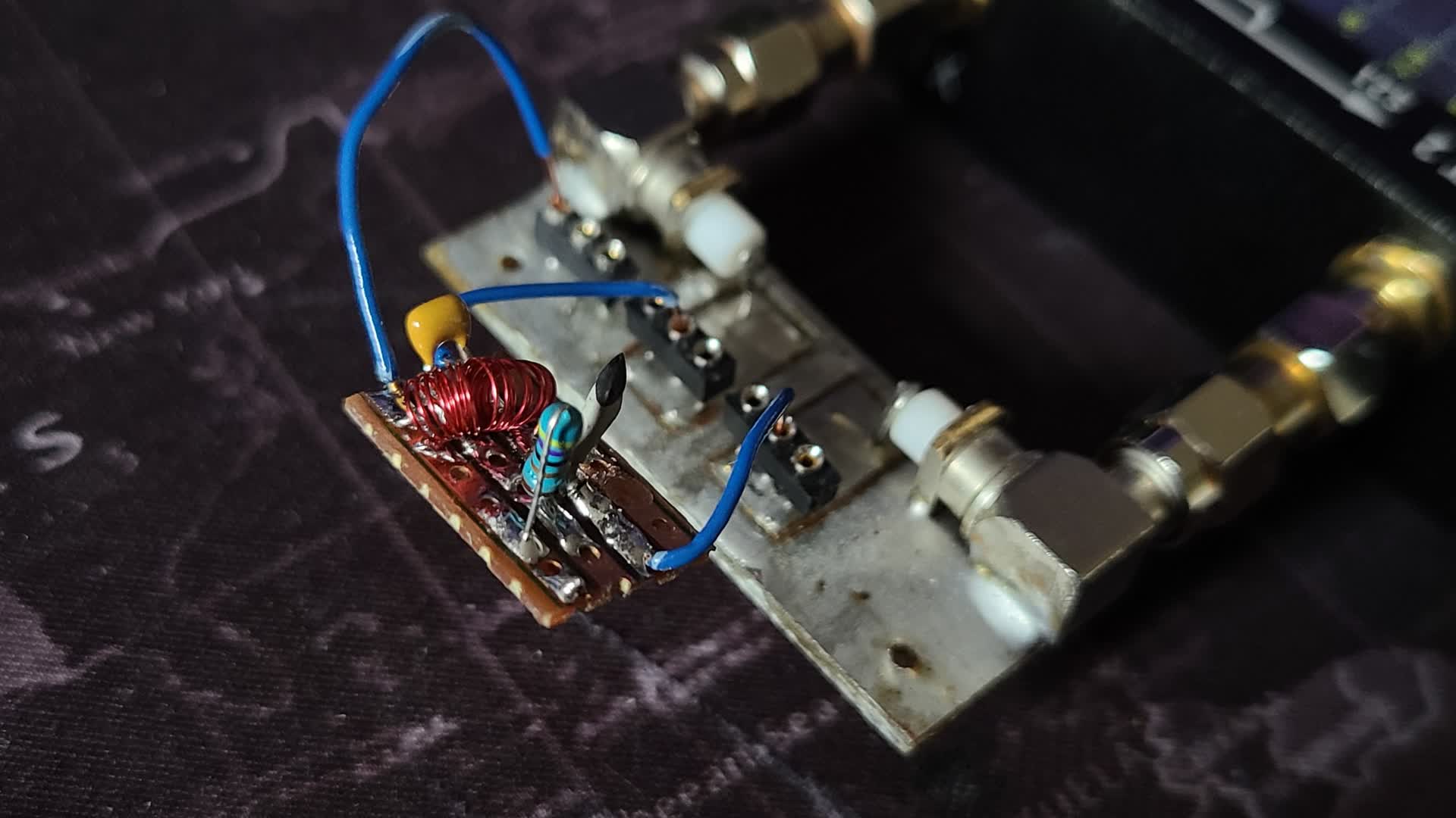
The first look at the diplexer yielded poor results due to the the 258 nH inductor. I hand-wound the inductor using 8 turns of 30 AWG on a 4mm form. This produces an inductance slightly lower than needed.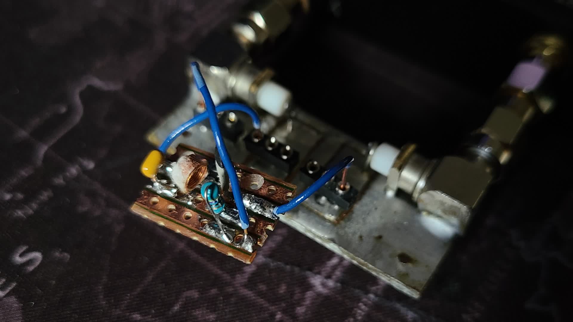
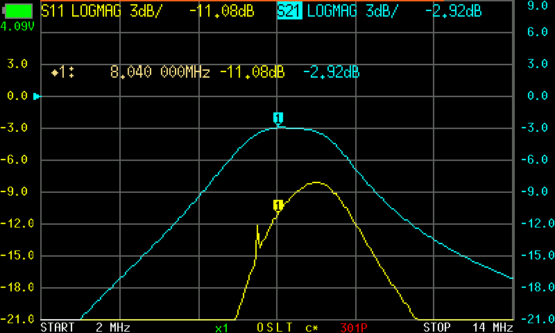
After the first test, I re-made the inductor. Using the same 4mm form, I wound 11 turns to achieve an inductance much greater than needed. With that, I can then separate the windings in place on the board to tune the diplexer.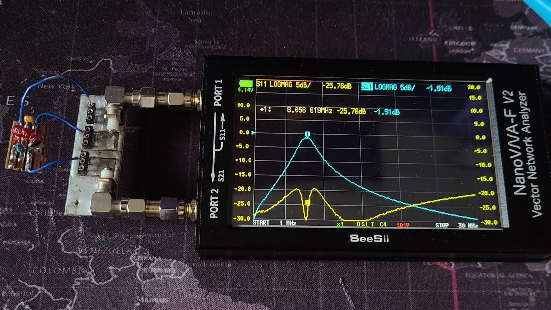
Looking into the diplexer from the output, the S22 reading shows the lack of constant impedance. This is normal operation for diplexers, however if a constant impedance is required at both ports, I will have to look into designing a reflectionless filter.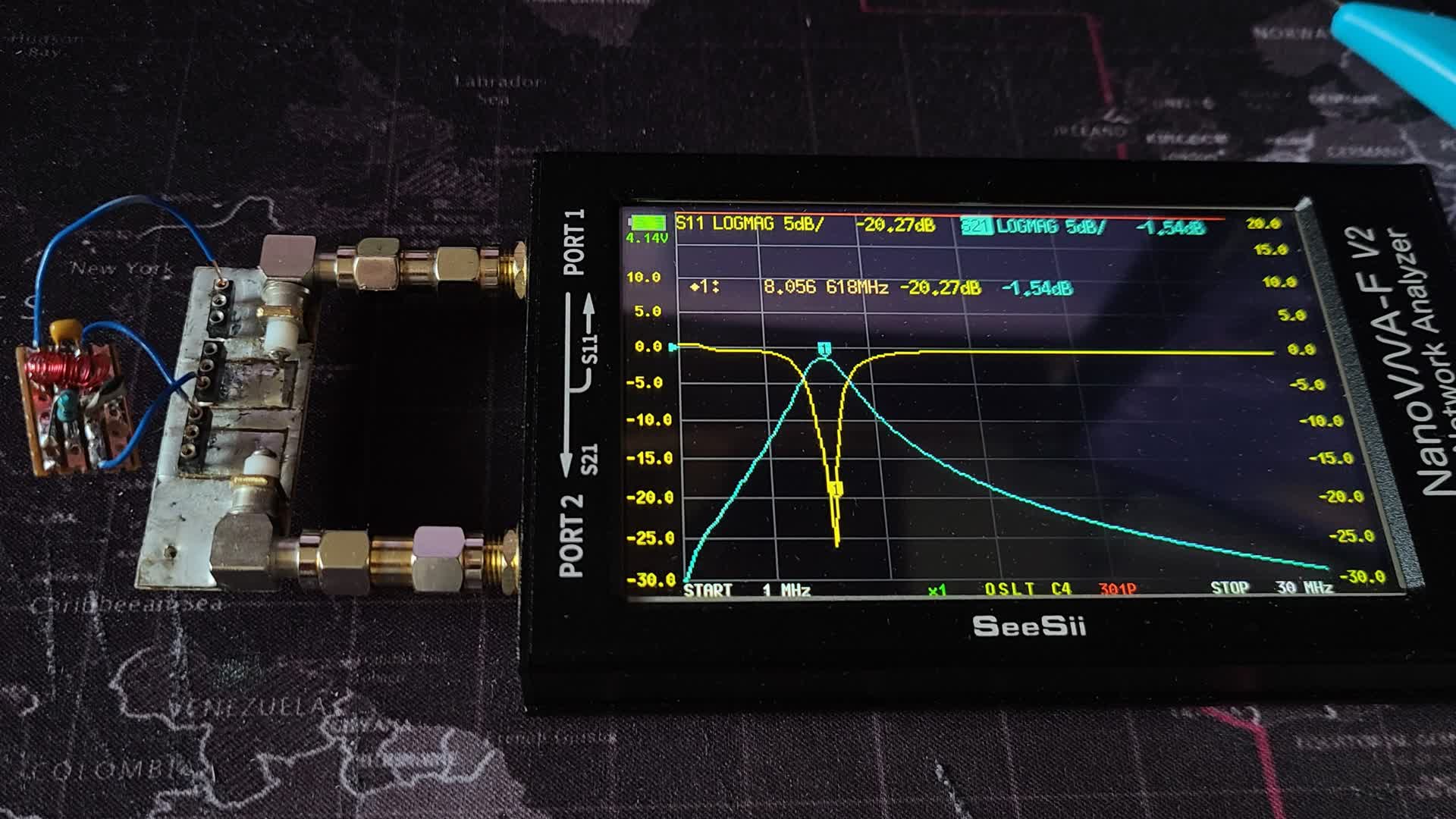
Remarks
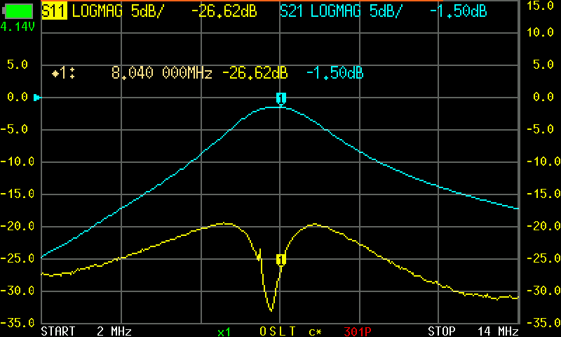
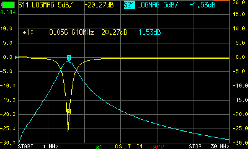
With the diplexer tuned to 8 MHz its performance is very good. The 4.7 uH SMD inductor I used on the series tank circuit may be the reason the circuit is presenting a 1.5 dB insertion loss as I never checked the inductors Q factor.
In the final version of this circuit I plan to use T37-6 iron core toroid inductors or air core chip inductors alongside NP0/C0G capacitors. I may also add in a trimmer capacitor to tune the parallel tank such that the input impedance is close to constant.