Working on my Vacuum Flourescent Display (VFD) filament driver, I realized I have no easy way to test the saturation current of my home made inductors. Characterizing the inductors core material is necessary to creating an efficient transformer, so I built a test unit based on the principles of inductance.
Inductor Saturation Tester
When you create a loop (or many loops) of wire in air, you have what is known as an air core inductor. These inductors are of a low value because of the low relative permeability of air (μr = 1.000). When making inductors with higher values, you would need to either create bigger loops, and more of them, or use a ferromagnetic core that has a higher permeability (μr > 1.000). In the case of a material like ferrite, the permeability can range from anything around the 10's to 1000's.
An inductor made with a core material has a few considerations that need to be taken into account however, the main one being saturation of the core. Core saturation occurs when the ferromagnetic core reaches its maximum magnetic flux density, after which, the core is then invisible to the inductor.
What this means is, if I push the inductor into saturation, I should expect to see a the inductance drop after it saturates. That is to say, the μr drops from the ferrites value (say 500 for example), down to about 1.000.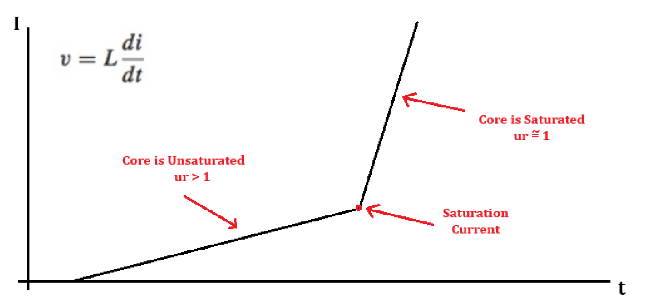
Implementation
To measure a cores saturation current, I first wanted to apply a constant voltage across the inductor. Then, by watching the current increase through the inductor over time, I can find that "knee" where the slope of current over time increases.
Being that applying a constant voltage will allow a large amount of current flow, the tester needs to have a controllable on-off time. To do that, I designed a pulse width modulator with fine control in the first few microseconds.
This was done using two 555 timers. The first 555 timer (U1) creates a very short trigger pulse at a frequency of around 20-50 Hz defined by the capacitor C1 and resistor R1. Then, the pulse duration control is done using a second 555 timer (U2). The pulse generated by U2 is triggered from the pulse of U1. Additionally, for synconizing the oscilloscope measurements there is an edge detector used for an external trigger signal.
The pulse duration is set using a 100 kohm linear potentiometer in series with a 1k resistor. Total pulse duration is able to be chosen (switched between short and long) by switching between capacitors C3 and C4.
The output pulse then drives a MOSFET, which sinks current from the inductor under test, into a 0.1 ohm sense resistor (R7).
Current measurement is taken as the voltage drop across R7, and shown on an oscilloscope.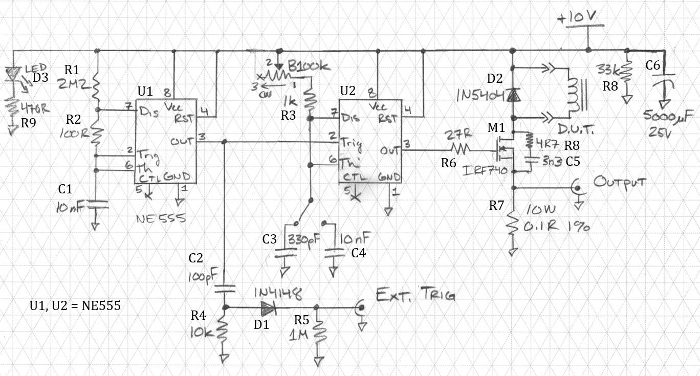
Construction
I first prototyped the circuit on a breadboard to make sure everything worked correctly.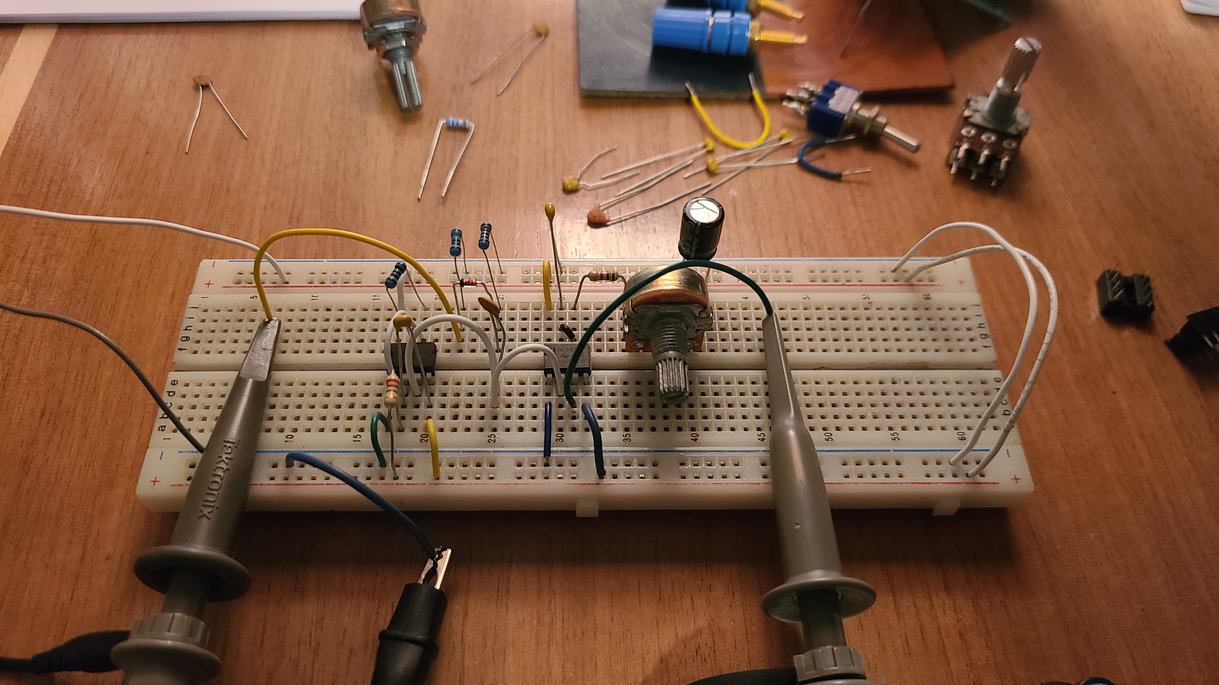
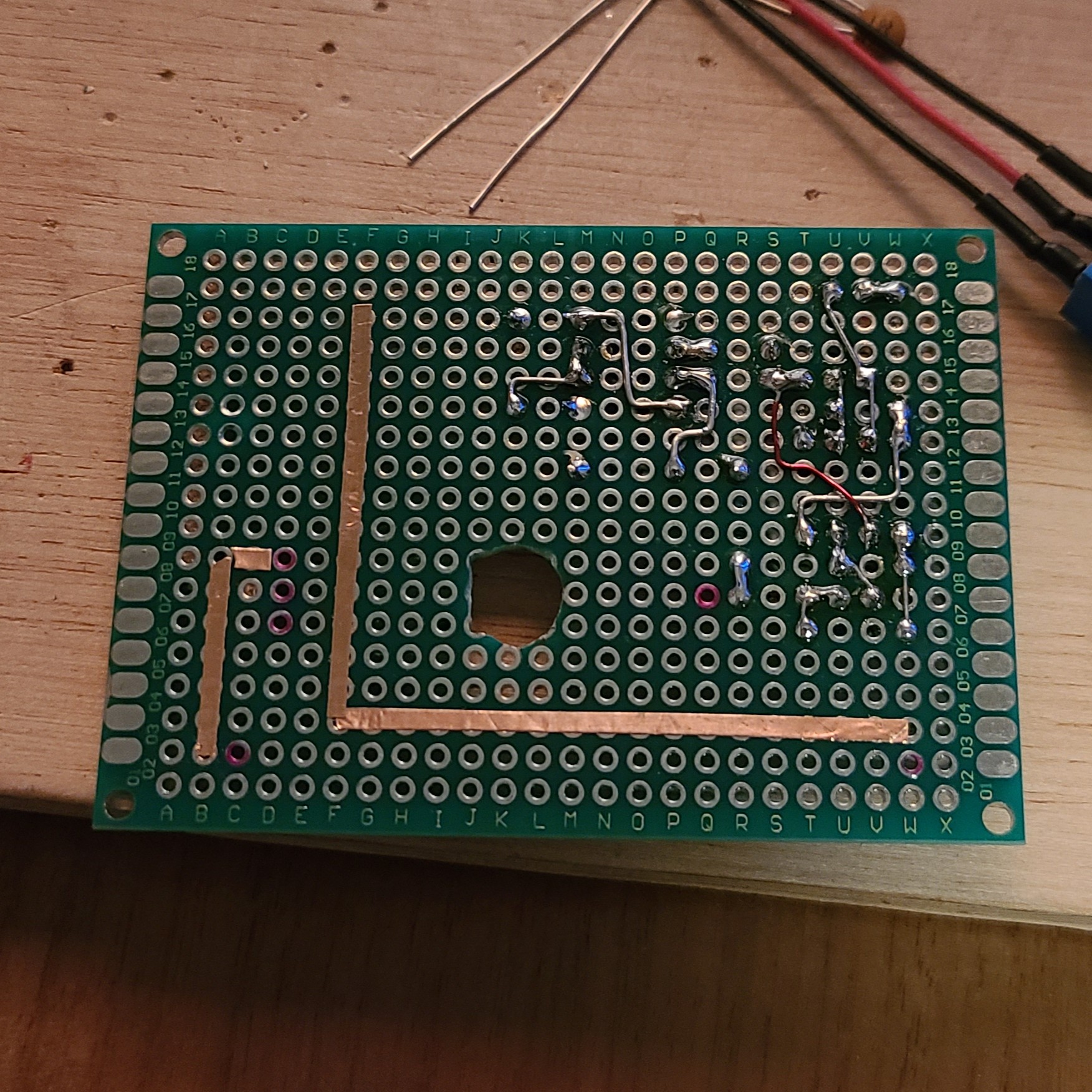
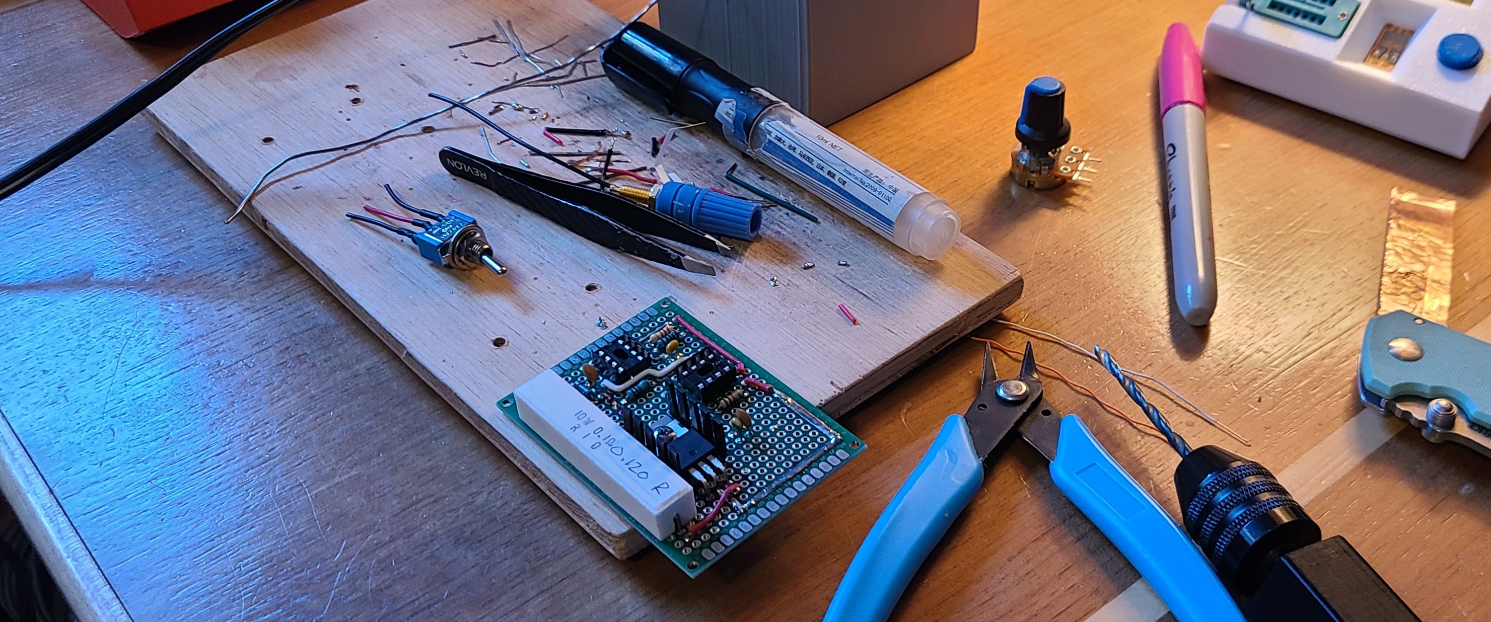
The circuit was build on some 50mm x 70mm proto-board. Using the components in the schematic, the board was soldered together.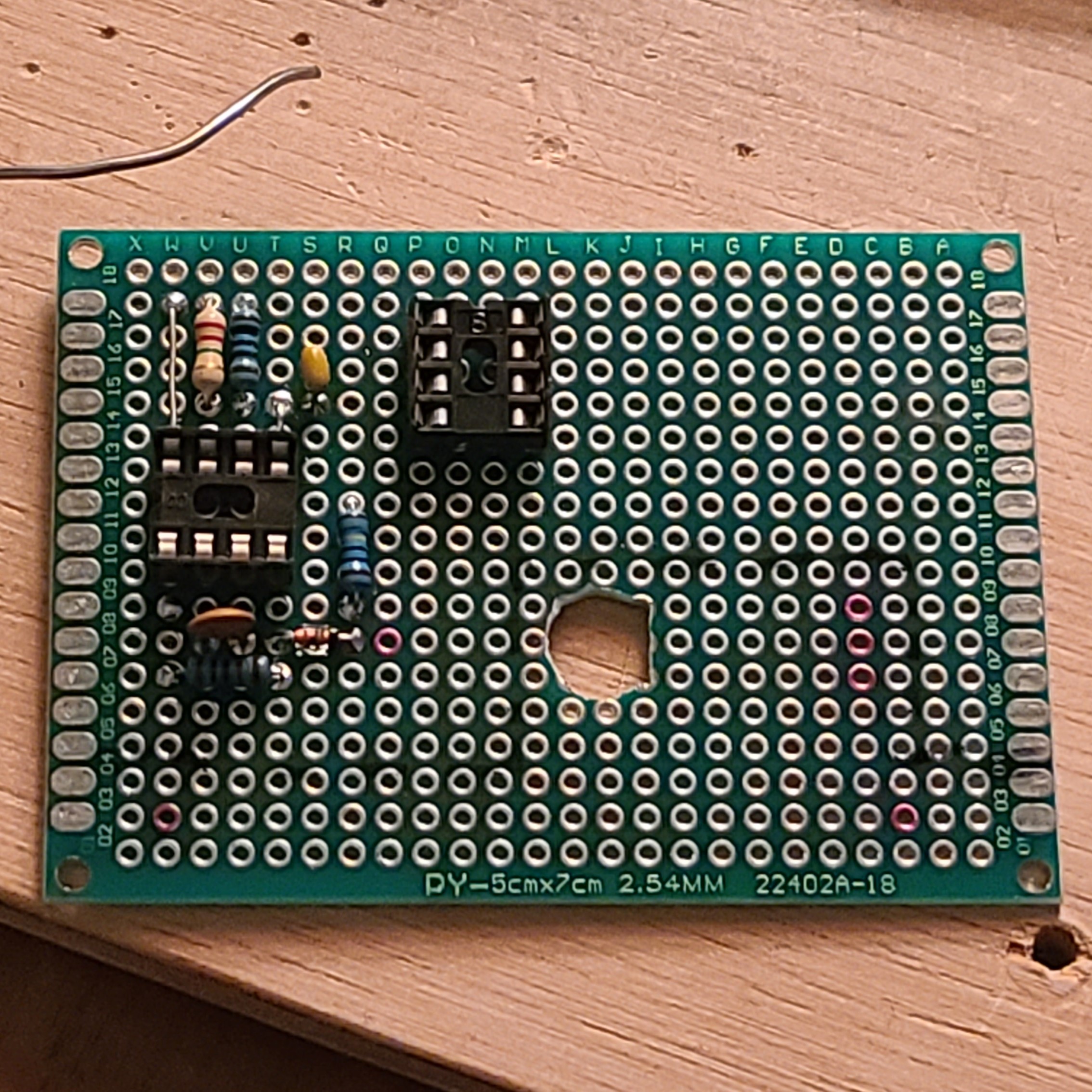
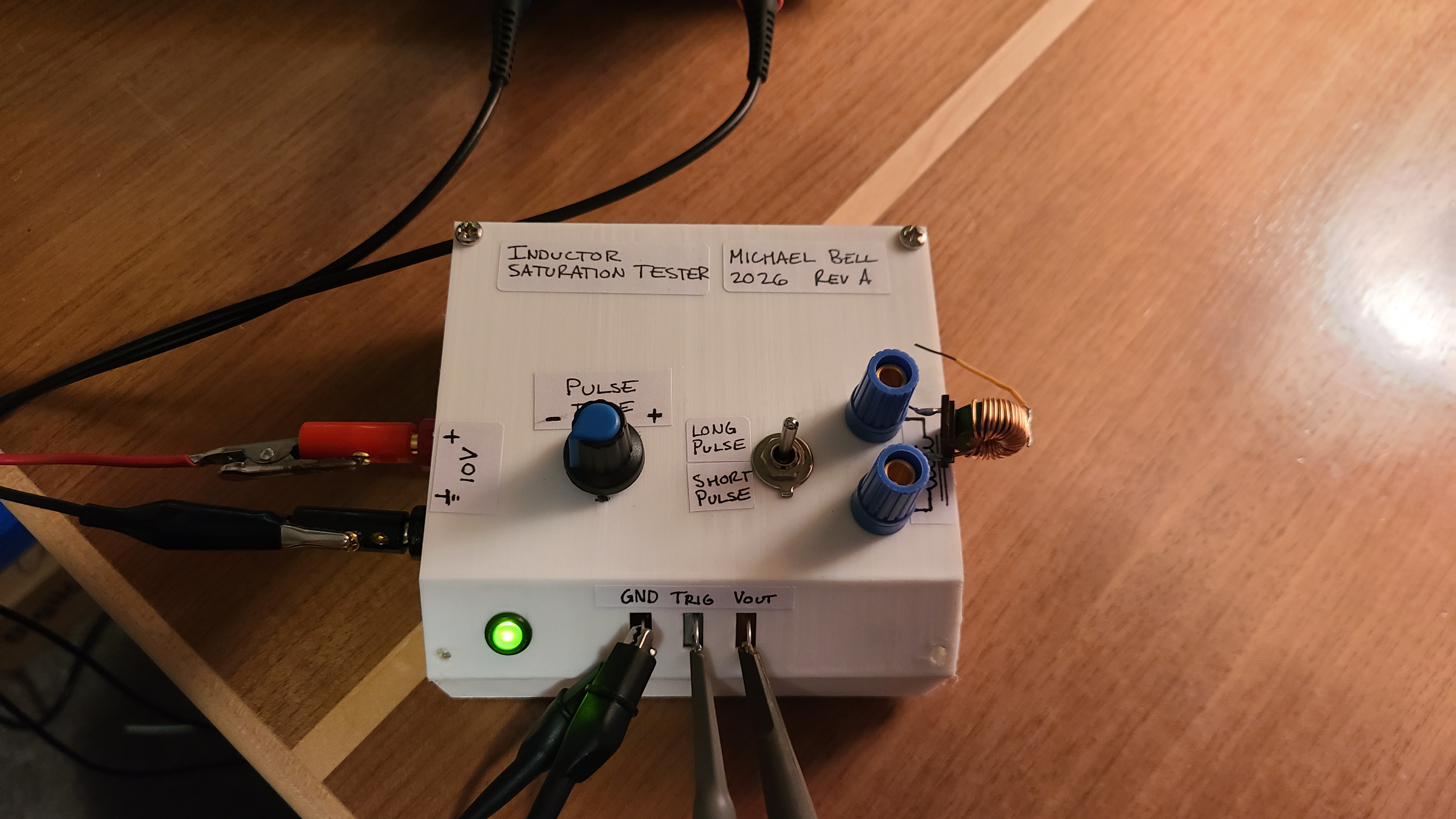
Next I completed the circuit and gave it a nice enclosure.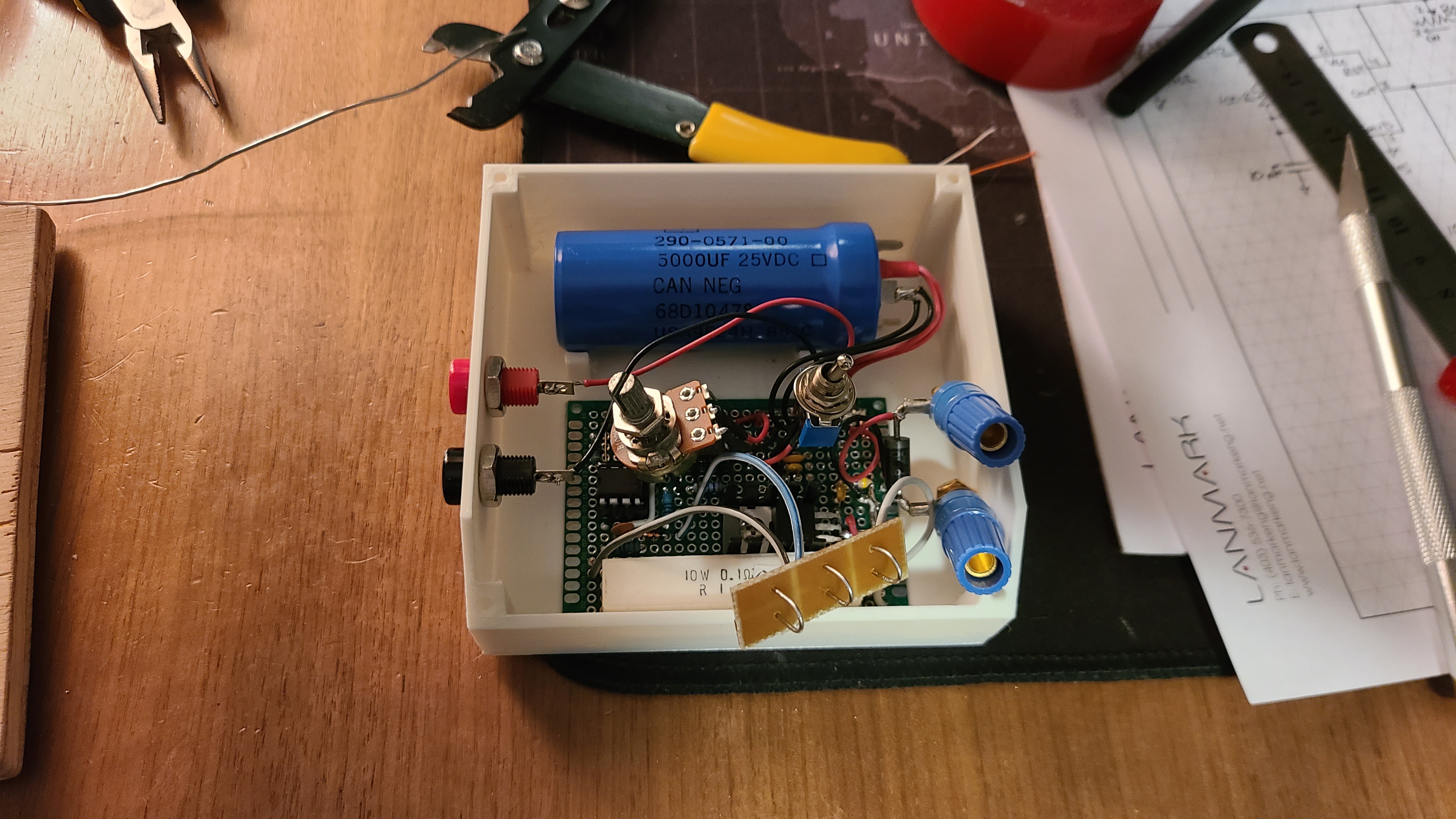
Testing the Results
After completing the build, I tested a number of inductors. First was this random 330uH inductor from the miscellaneous pile. This inductor has a clear elbow between unsaturated and saturated.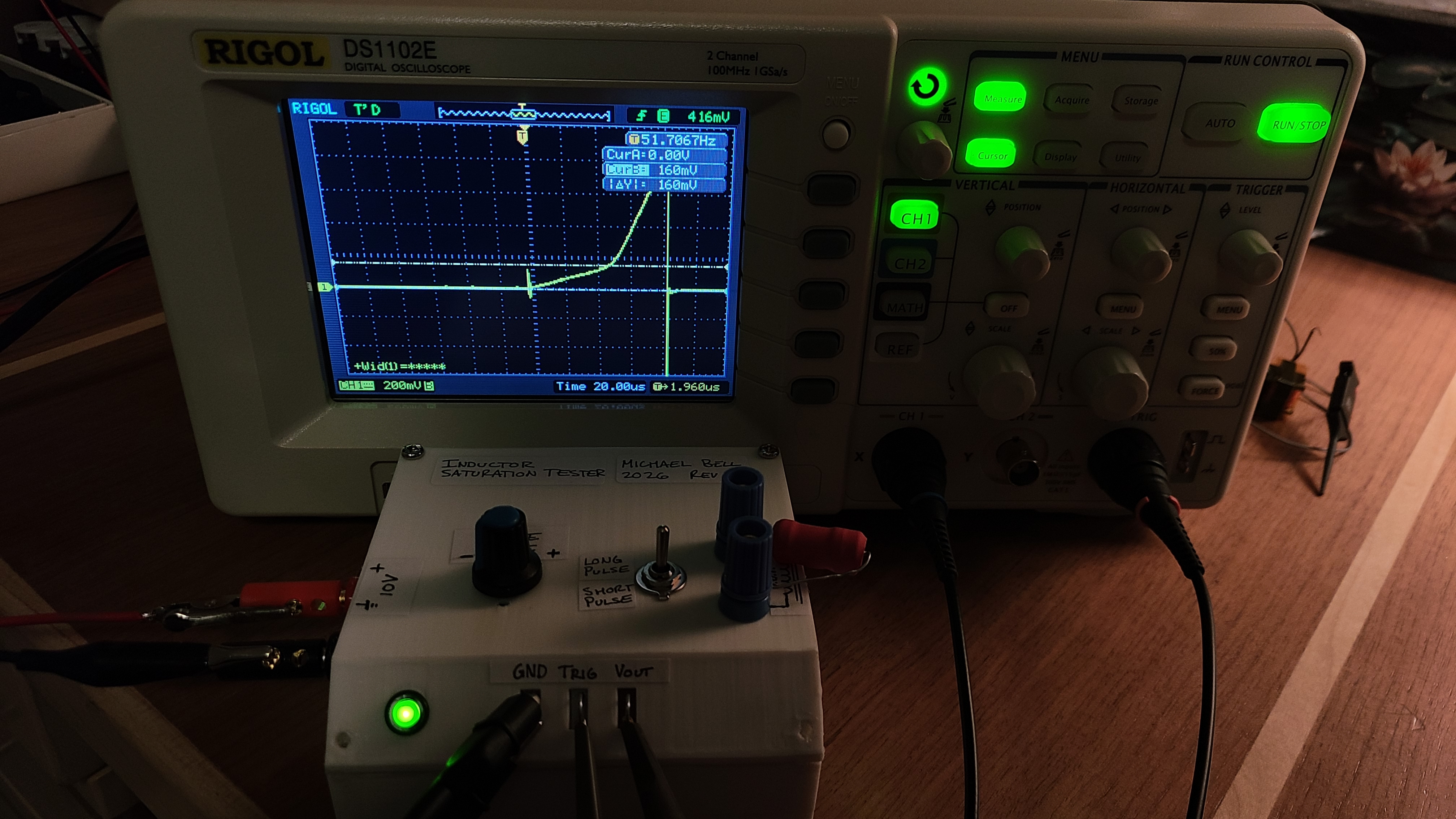
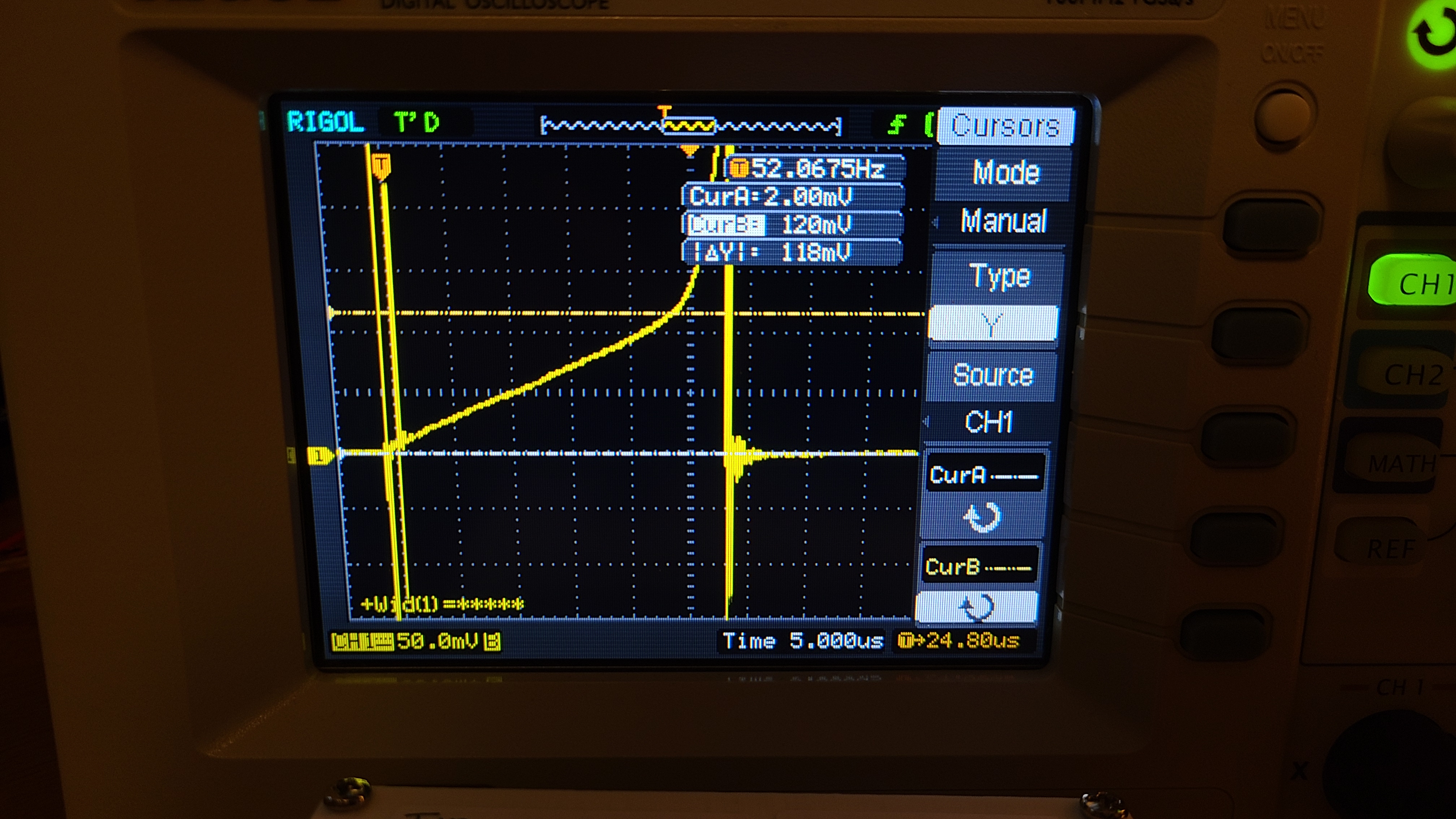
Testing another inductor (EP transformer core, 40 turns), the elbow was much smoother and harder to determine a point. In this case, manufacturers would usually specify 10% or 30% saturated on their datasheets.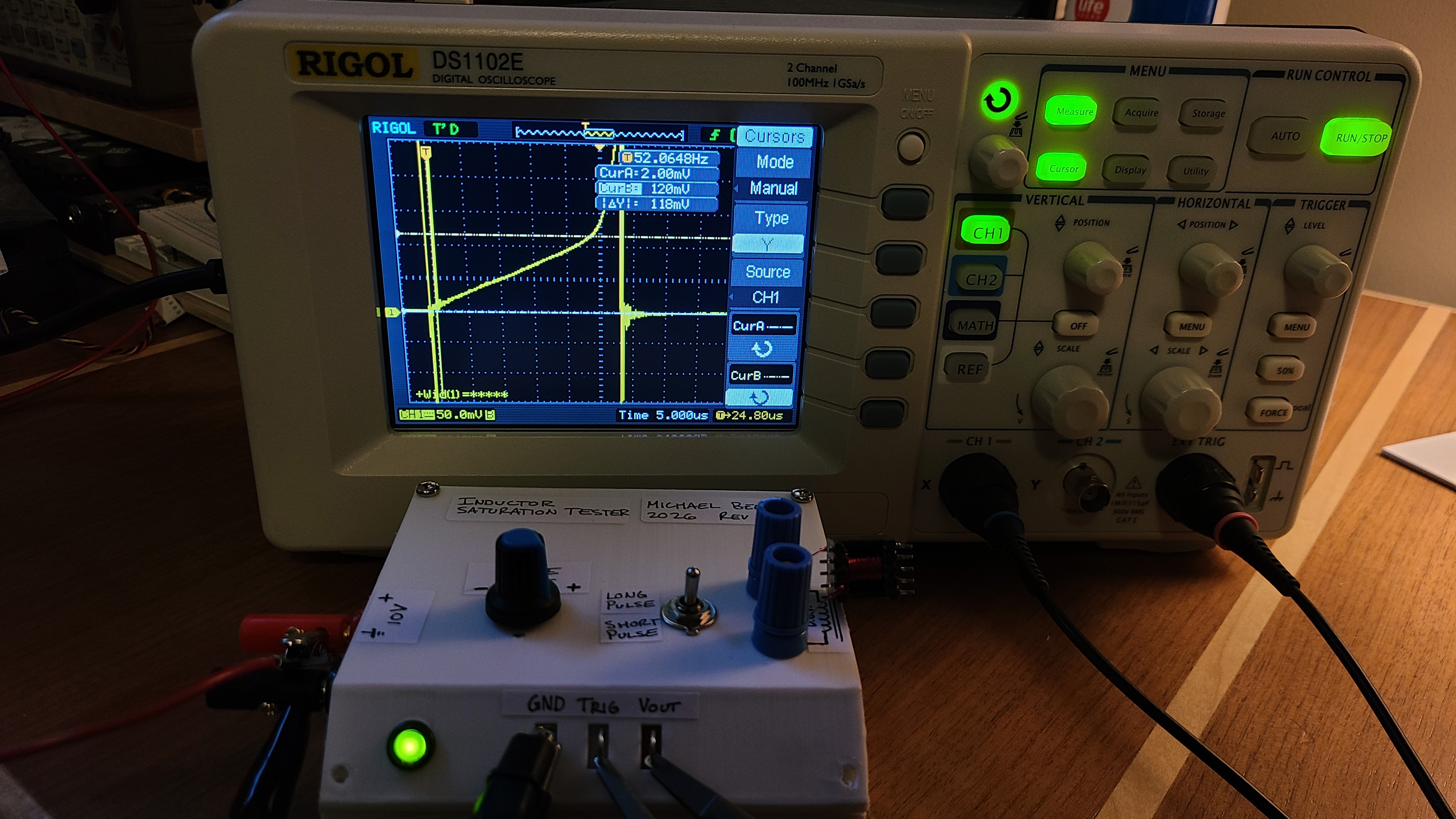
Remarks
This tool was super simple to create, and should come in handy for future projects - especially when designing power delivery systems.