Having acquired more knowledge on amplifier configurations and properties, I redesigned the front-end amplifier. This time using a common base as the first stage, then common emitter as a second stage, with a common collector at the output to match the impedance to 50 ohms for the VNA measurements.
Front-end Amplifier
Design and Simulation
I decided to not include the bandpass filter in this design, as it can be included later on.
Initially, I hand calculated the values for each stage, using the input impedance and bias point as a starting point. The gain of the first stage was calculated to be around 22dB, and the second stage around 10dB. The common collector stage causes some loss in gain as well. Overall the target gain of the amplifier is about 30dB.
The circuit was simulated in LTspice shown in the images below. Using -20uV as an input (-100dB), the gains were confirmed.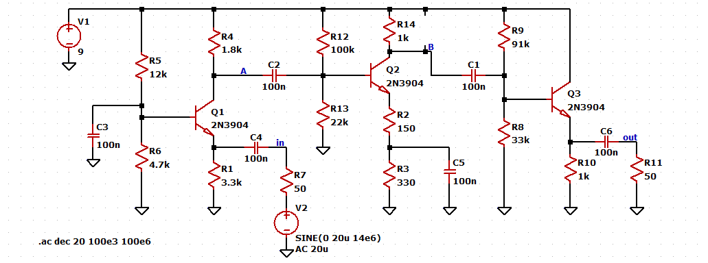

At the frequency band of interest (14.00 MHz to 14.35 MHz), the AC analysis shows a total gain of approximately 31dB.
Prototype
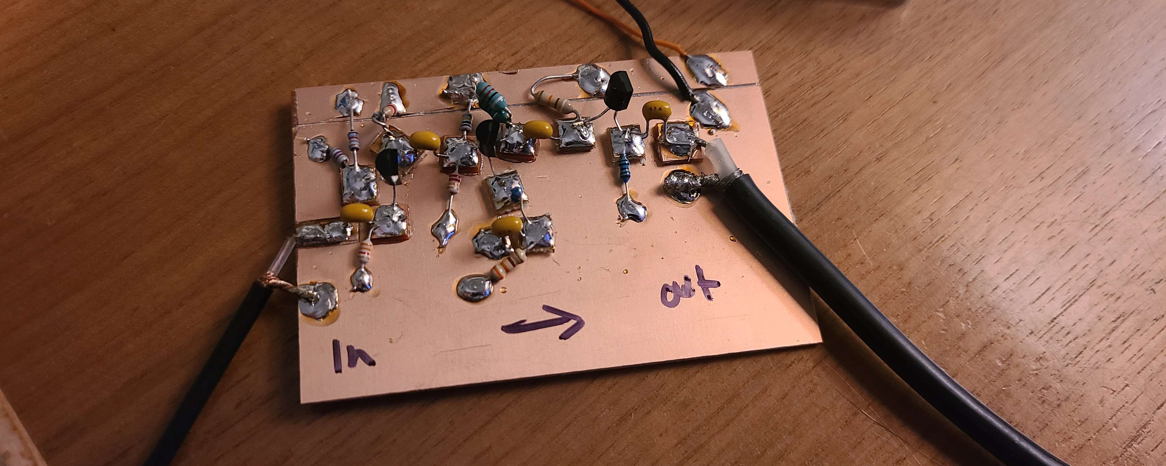
I put together the circuit on a piece of copper clad board like the previous amplifer build. After powering up the circuit to 9V, the DC bias points were tested and matched fairly close to the simulation results.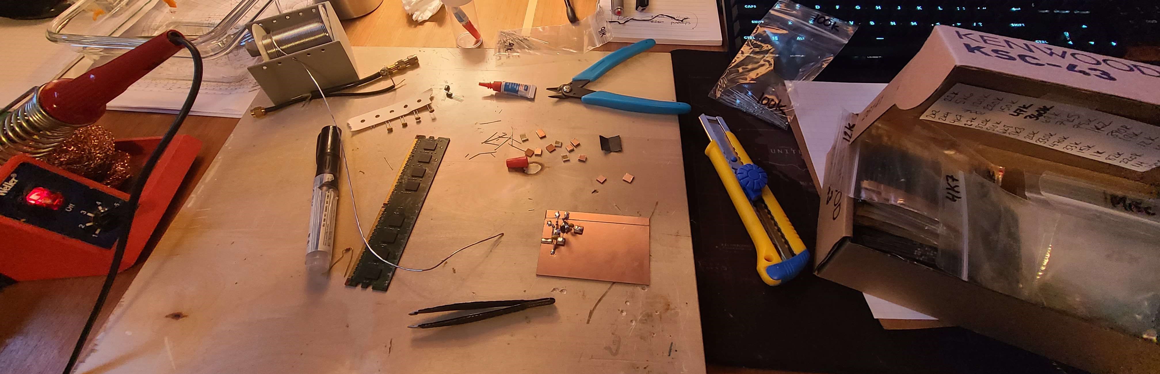
I connected the amplifier to my NanoVNA to check both the input and output impedances, as well as overall gain.
A lesson I have learned in the process was that the NanoVNA outputs a pulse with a magnitude of around -11dBm which at 50 ohms is 178 mV peak to peak. This means that an amplifier with a significant gain would overload the S21 (through) input. With that now known, I added a simple pi-network attenuator at the input (soldered onto the board). This attenuator was measured to be about 25.8dB of attenuation.
With the 25.8dB of attenuation in addition to my homebrew 10dB attenuator, the total gain of the amplifier could be calculated.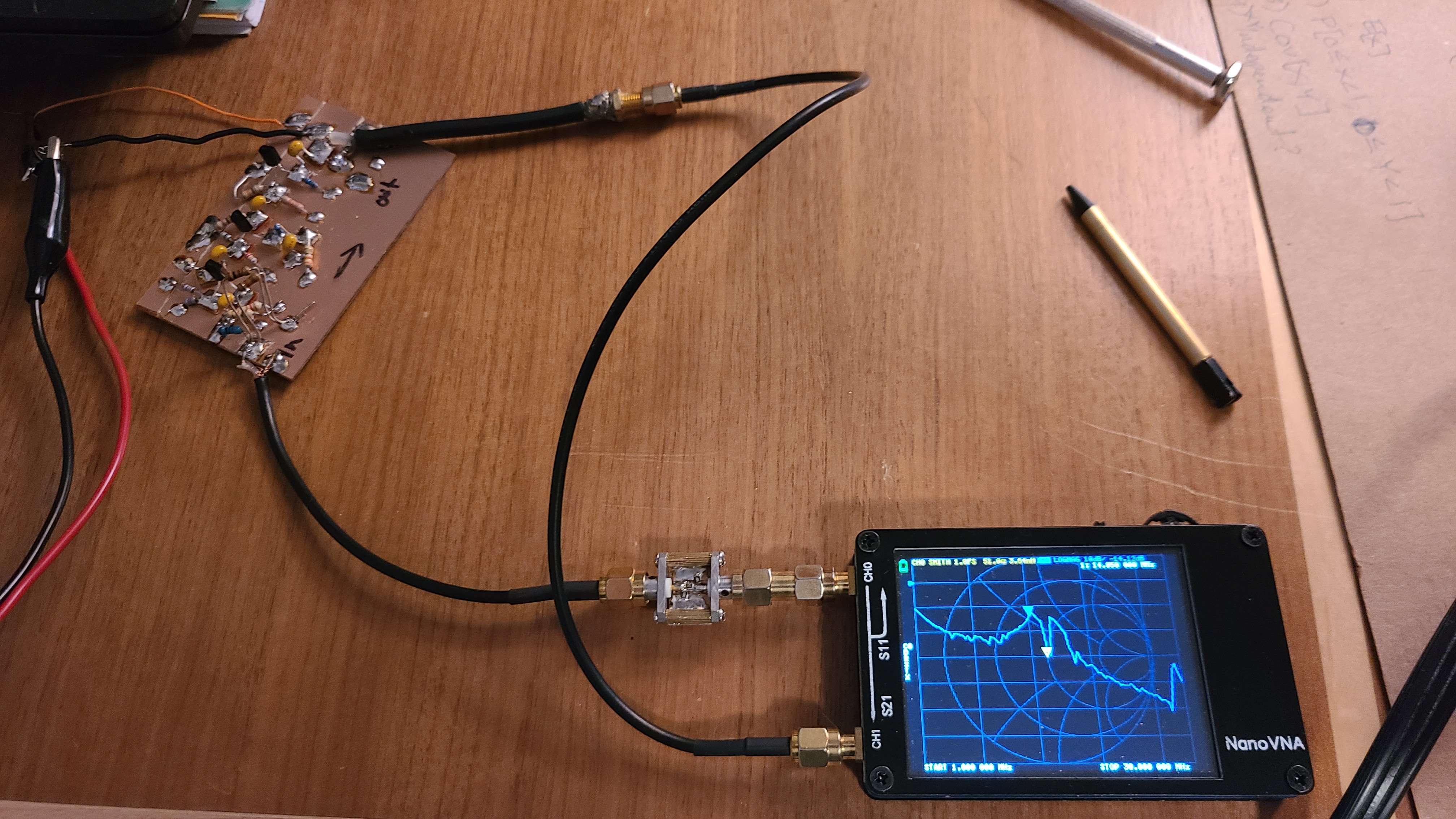
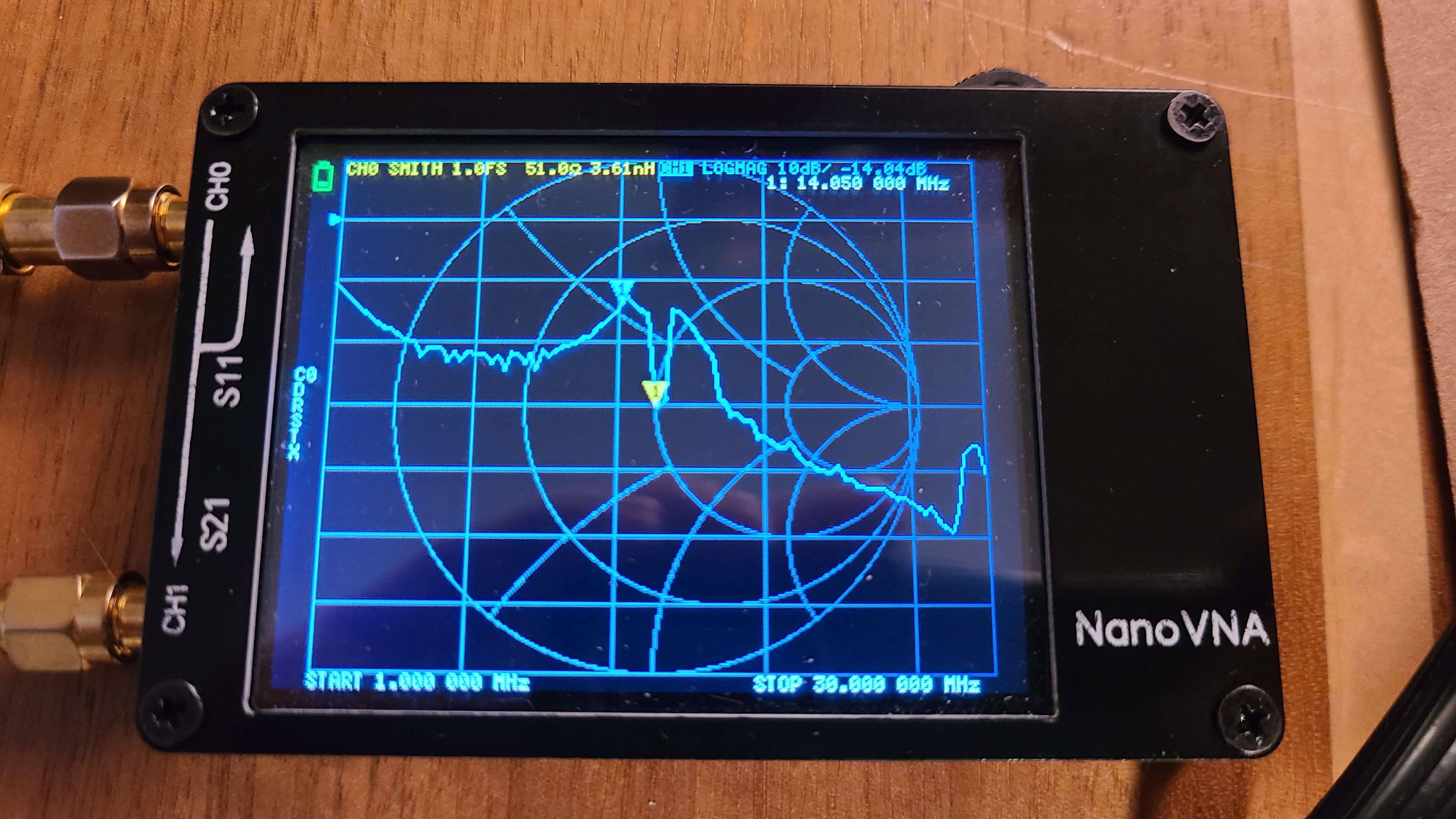
At the desired frequency band of 14.00 MHz to 14.35 MHz the gain was measured at approximately 21dB.
Once again this is close to the simulation, but not quite ideal. Which means it's back to the drawing board.
Remarks
I think keeping the common base stage as is would be fine, but I noticed the common emitter stage is falling victim to the miller effect significantly. Maybe adding some feedback could reduce it's effects, or changing it to a cascode amplifier stage.
I might also reduce the overall gain of each stage to further improve the characteristics.
We will see in the coming weeks.