After the two previous designs, I decided to purchase some transistors rated for a higher frequency. This is a more pay-to-win approach to my previous issues, but works nonetheless. An additional bonus is the noise figure of the new transistors being significantly lower.
Design
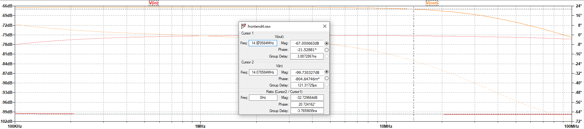
Calculations and Simulation
I started my design by having a common base (CB) input stage to match to the 50 ohm input impedance. The transistor I chose for this was a newly purchased BFR193. The common base stage operates with a collector current of 500 mA. The collector resistor chosen was 3.3k ohms.
Next I buffered the output of the CB amplifier with a common collector (CC) amplifier using the KSP10TA BJT. The transistor selection was mainly driven by the fact that I purchased the KSP10TA at the same time as the BFR193 and I wanted to try out both of them. This stage was set to have an input impedance greater than the output of the CB stage, and the output impedance was set to be close to 50 ohms. Transistor LTSpice Models For the sake of documentation and the fact that these models were not particularily easy to find, I am providing them here. OnSemi KSP10TA Model Infineon BFR193 Model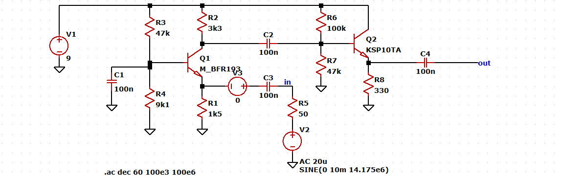
.MODEL KSP10TA NPN(
+ IS = 1E-11
+ ISE = 70E-11
+ NE = 2.5
+ VAF = 100
+ BF = 110
+ NF = 1.3
+ IKF = 0.065
+ NK = 0.45
+ XTB = 0
+ BR = 3
+ CJC = 1.56E-12
+ CJE = 2E-12
+ TR = 50E-9
+ TF = 1.85E-10
+ ITF = 0
+ VTF = 0
+ XTF = 0
+ RB = 42
+ RC = 0.3
+ RE = 0.2
+ Vceo = 25
+ Icrating = 100m
+ mfg = OnSemi).MODEL M_BFR193 NPN(
+ IS = 8.17971E-016
+ BF = 108.285
+ NF = 1.003
+ VAF = 36.5472
+ IKF = 0.273876
+ ISE = 6.20271E-016
+ NE = 1.553
+ BR = 42.76
+ NR = 0.9775
+ VAR = 28.4
+ IKR = 0.01296
+ ISC = 3.44E-015
+ NC = 1.338
+ RB = 1.75232
+ IRB = 0.0001443
+ RBM = 0.967481
+ RE = 0.310454
+ RC = 0.133617
+ XTB = 1.303
+ EG = 1.11
+ XTI = 6.548
+ CJE = 2.126E-012
+ VJE = 1.052
+ MJE = 0.47
+ TF = 1.58062E-011
+ XTF = 0.0395
+ VTF = 0.0696445
+ ITF = 0.00207564
+ PTF = 0.0817673
+ CJC = 7.142E-013
+ VJC = 0.6315
+ MJC = 0.3991
+ XCJC = 0.1208
+ TR = 1.58463E-008
+ CJS = 0
+ MJS = 0
+ VJS = 0.75
+ FC = 0.675369
+ KF = 0
+ AF = 1
+ mfg = Infinion)
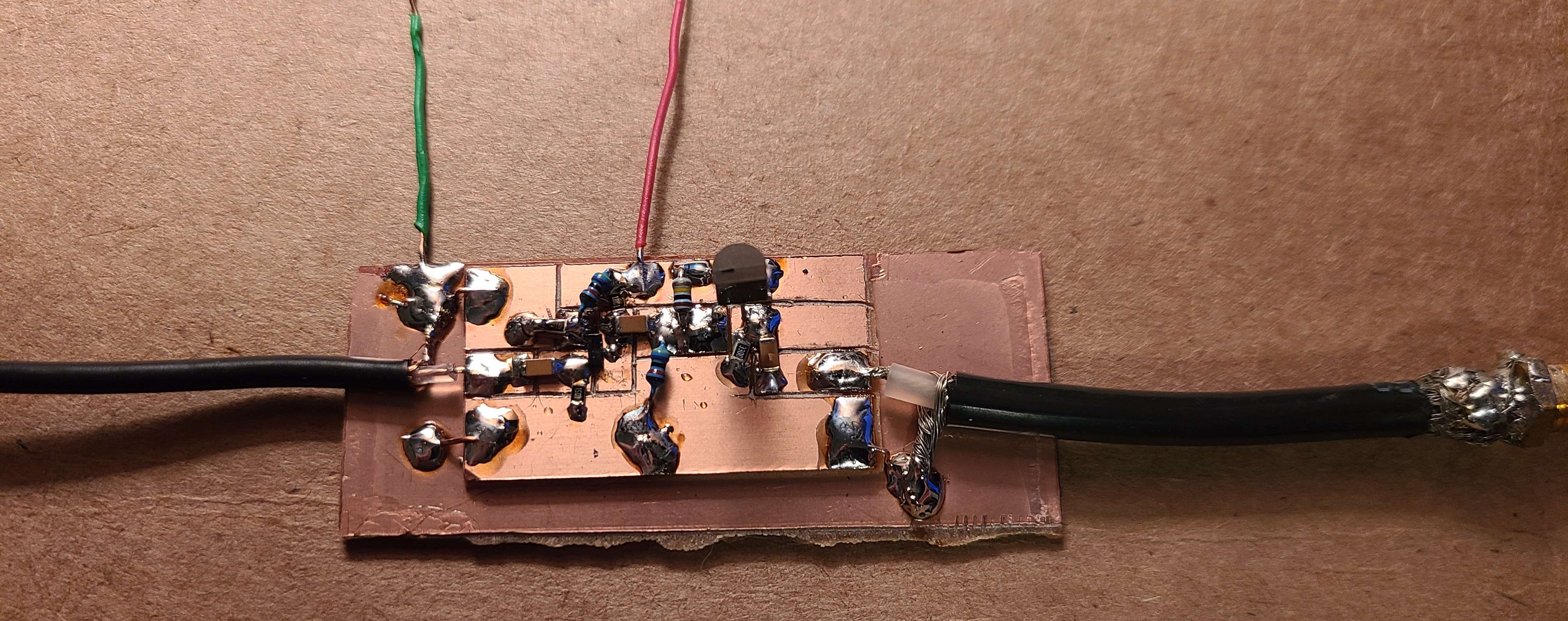
Construction
Onto the construction and testing of this filter design, I used a piece of copper clad board on a bakelite substrate (cheap and easy to scribe). I then soldered the parts onto the board.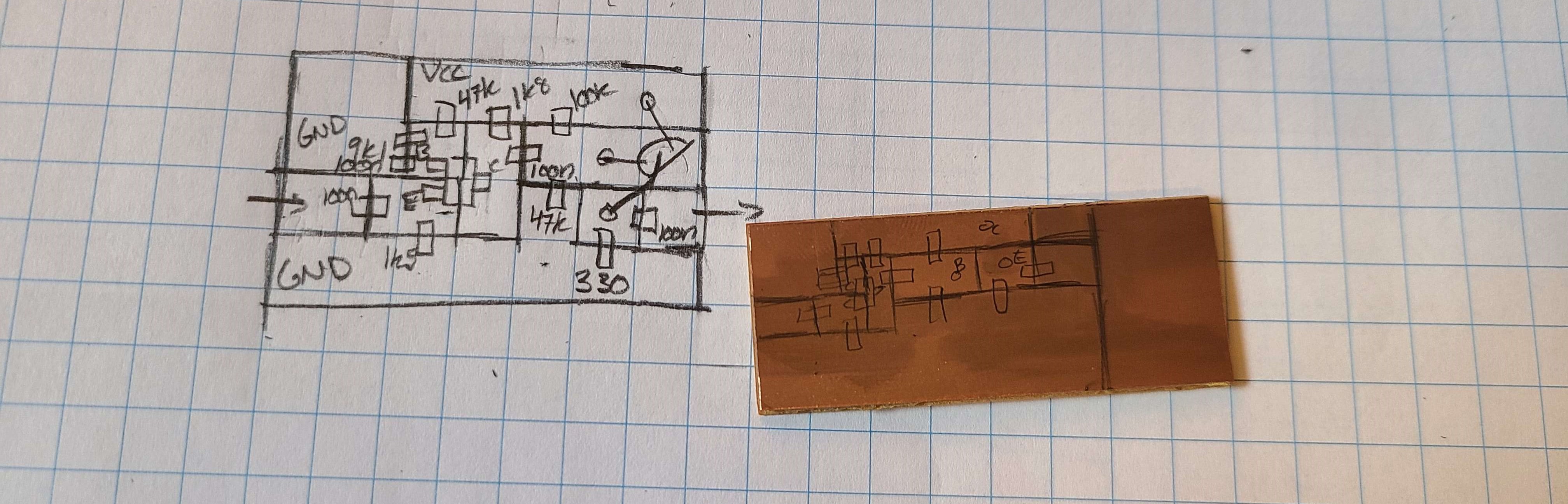
Testing
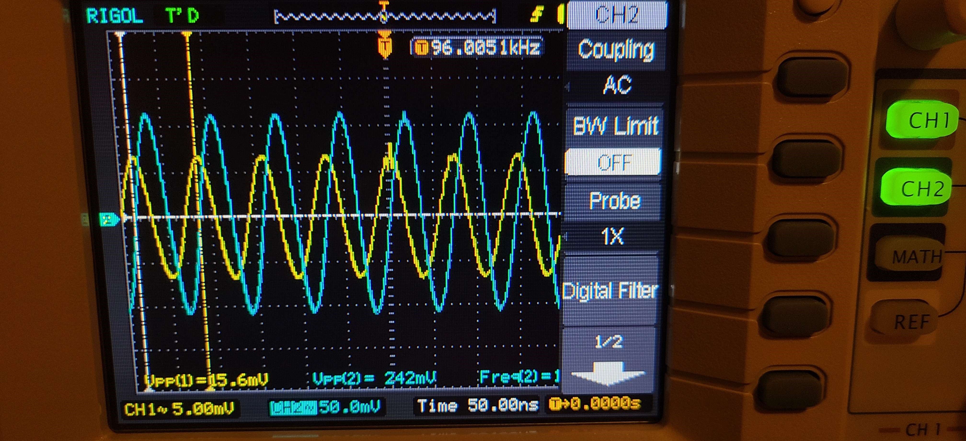
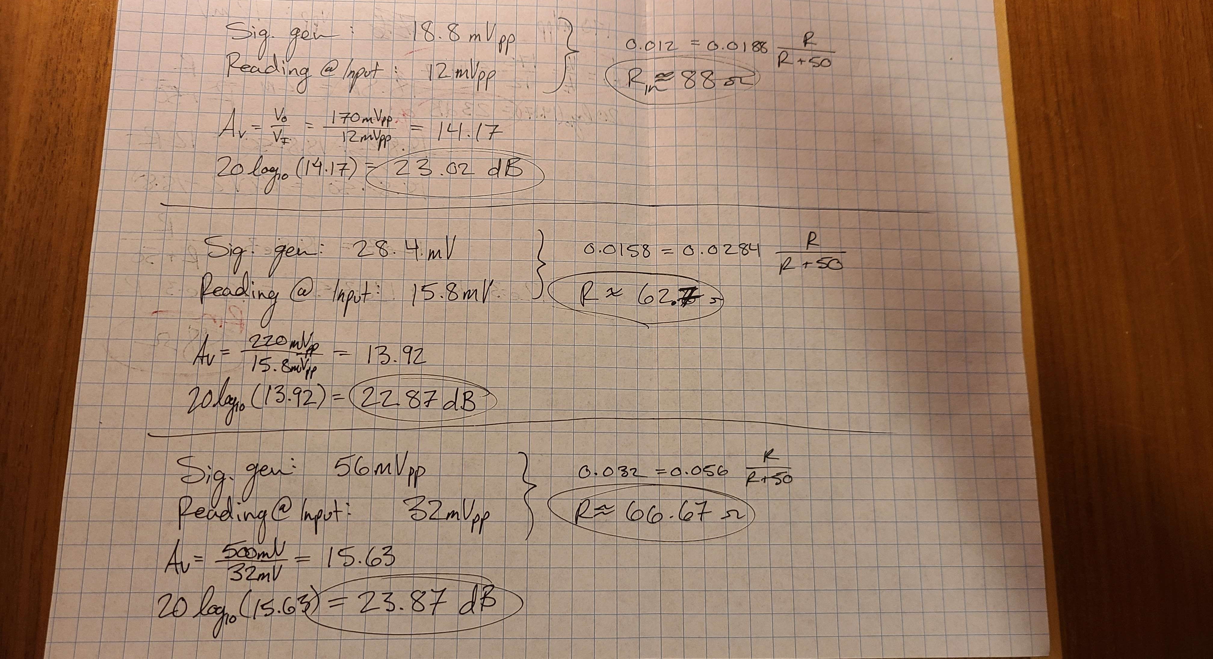
I tested the amplifier using the function generator and oscilloscope to measure the gain at my desired frequency of operation. Using measured results from a couple of different input amplitudes, I was able to calculate the gain to be in the range of 23 dB.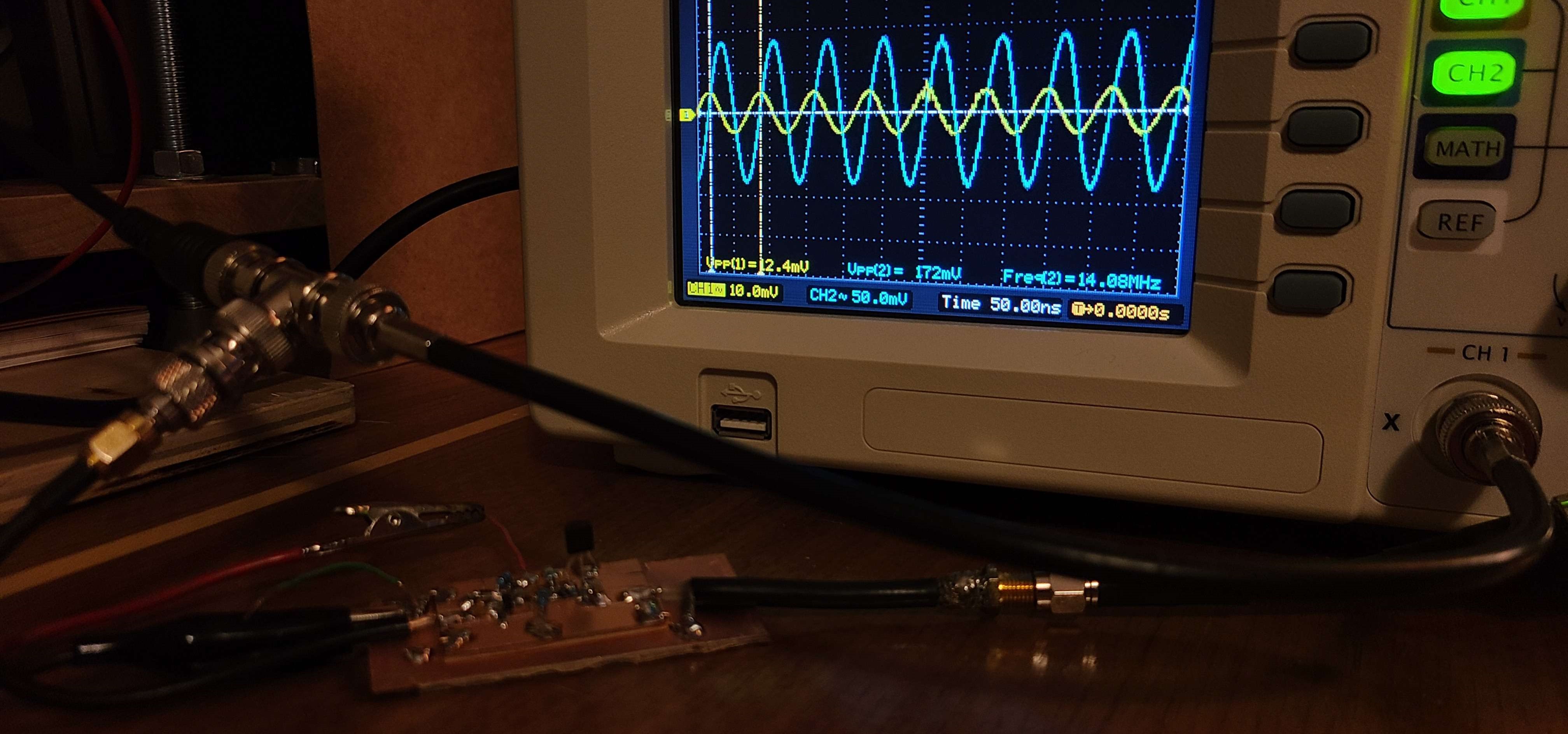
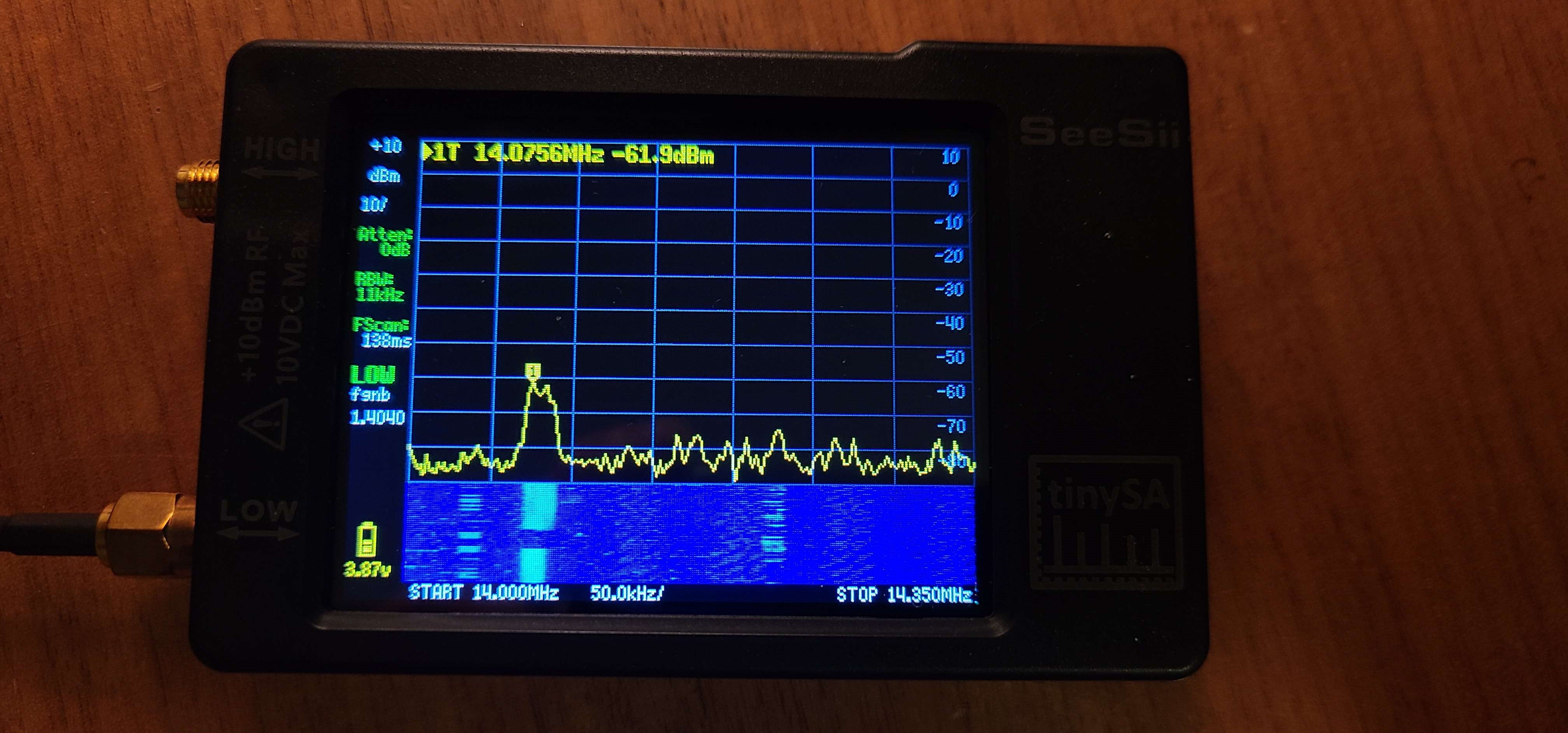
After testing, I connected the amplifier to the antenna I have outside (20m band inverted V dipole) and measured the output on my TinySA spectrum analyzer with the waterfall display enabled. I was able to visualize the 23 dB amplification when connecting and disconnecting the amplifier from the system.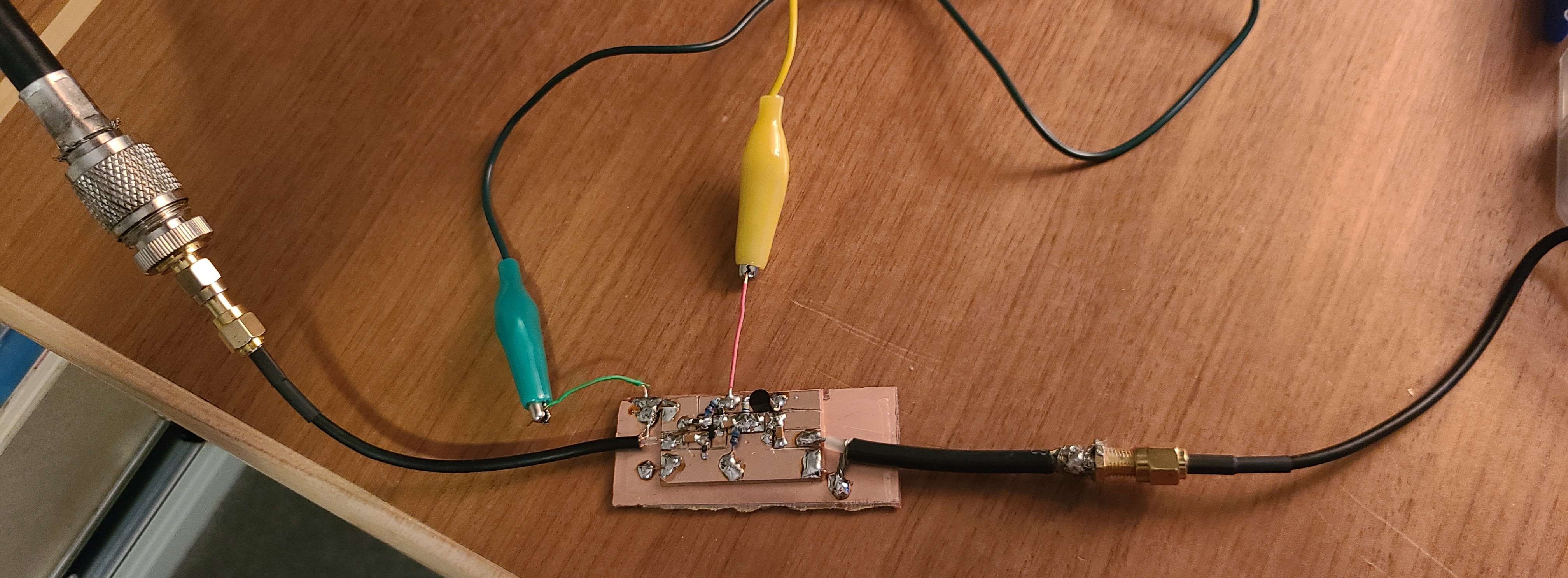
I attached the amplifier to my Yeasu HF radio to see if the amplifier introduces any excessive noise, and when running off a 9V battery, the noise was extremely low.
Remarks
The discrepencies between the simulated gain and measured gains could likely be due to a mismatch in impedances, or component tolerances not working in my favour. I may have another go at designing another amplifier, but for now I am quite pleased with 23 dB.