With the ongoing superheterodyne reciever project, I designed and simulated a recieve amplifier to amplify the signals coming from the antenna. I have chosen to use a bipolar junction transistor in the common emitter configuration as my amplifier.
Front-End Amplifier
Design and Simulation
I started by designing the input band-pass filter and matching network to convert the 50 ohm impedance of the input and antenna to 200 ohms for the amplifier.
I then designed the common emitter amplifier to have an input impedance of 200 ohms, and added a common collector output voltage follower stage.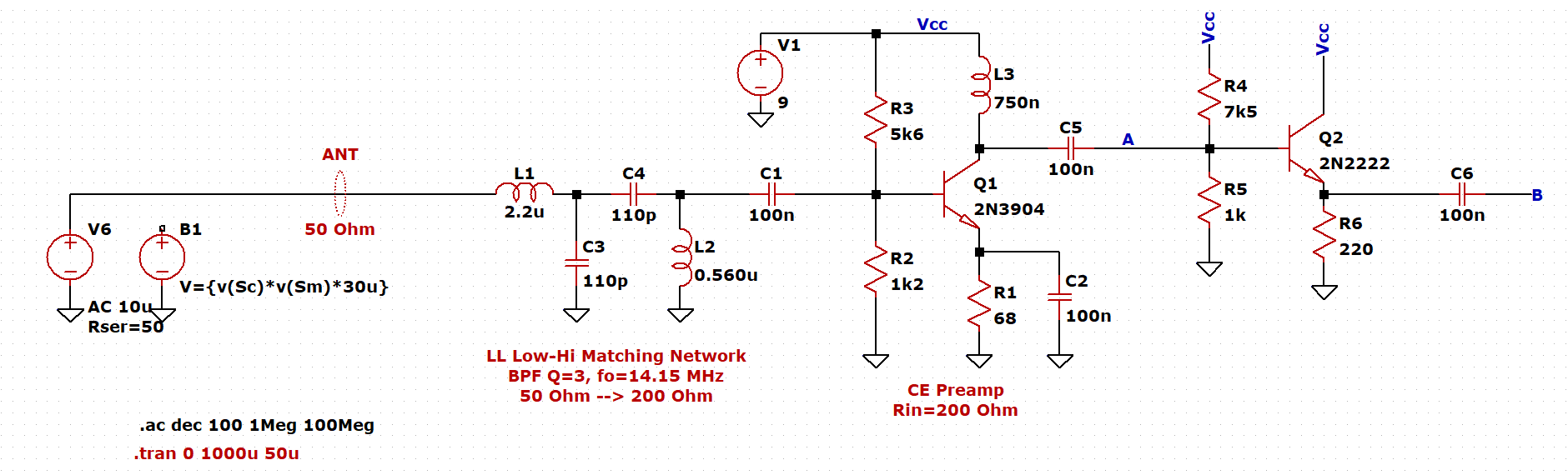
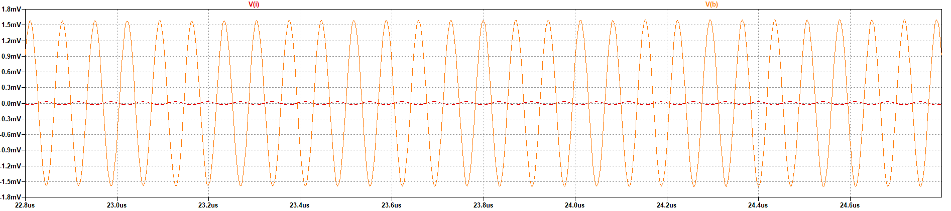
I then run the simulation using a 10 uV AC source for the AC simulation, and a 30 uV 14.15 kHz sine wave multiplied with a 10 kHz sine wave to simulate a recieved DSB-SC signal.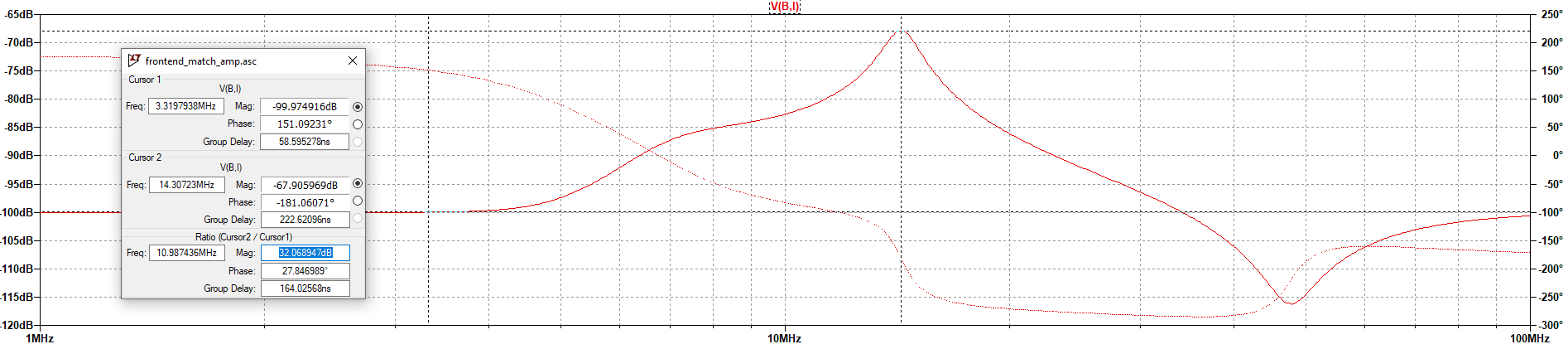
At the frequency band of interest (14.00 MHz to 14.35 MHz), the AC analysis shows a gain of 30dB. This is quite a large gain so I am sceptical of the performance I will achieve in practice, but it is quite impressive.
Prototype
I put together the circuit on a piece of copper clad board. Using parts I had on hand, I had to make some parts such as the 68R resistor (from a 47R in series with a 22R) and the inductors on the input matching filter (which may have been a poor decision I will touch on later).
Overall the circuit worked properly, with the DC bias points matching fairly close to the simulation results. I connected power and the function generator to the amplifier to check the gain.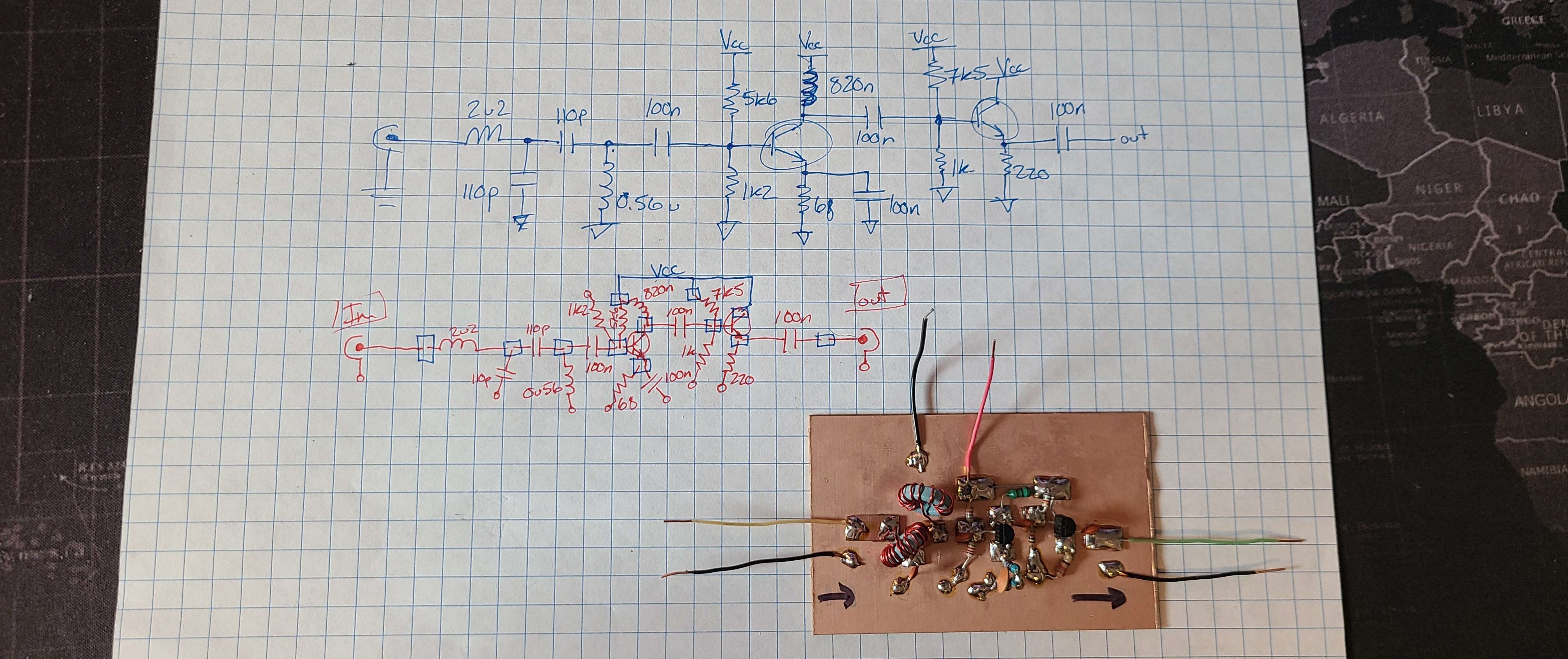
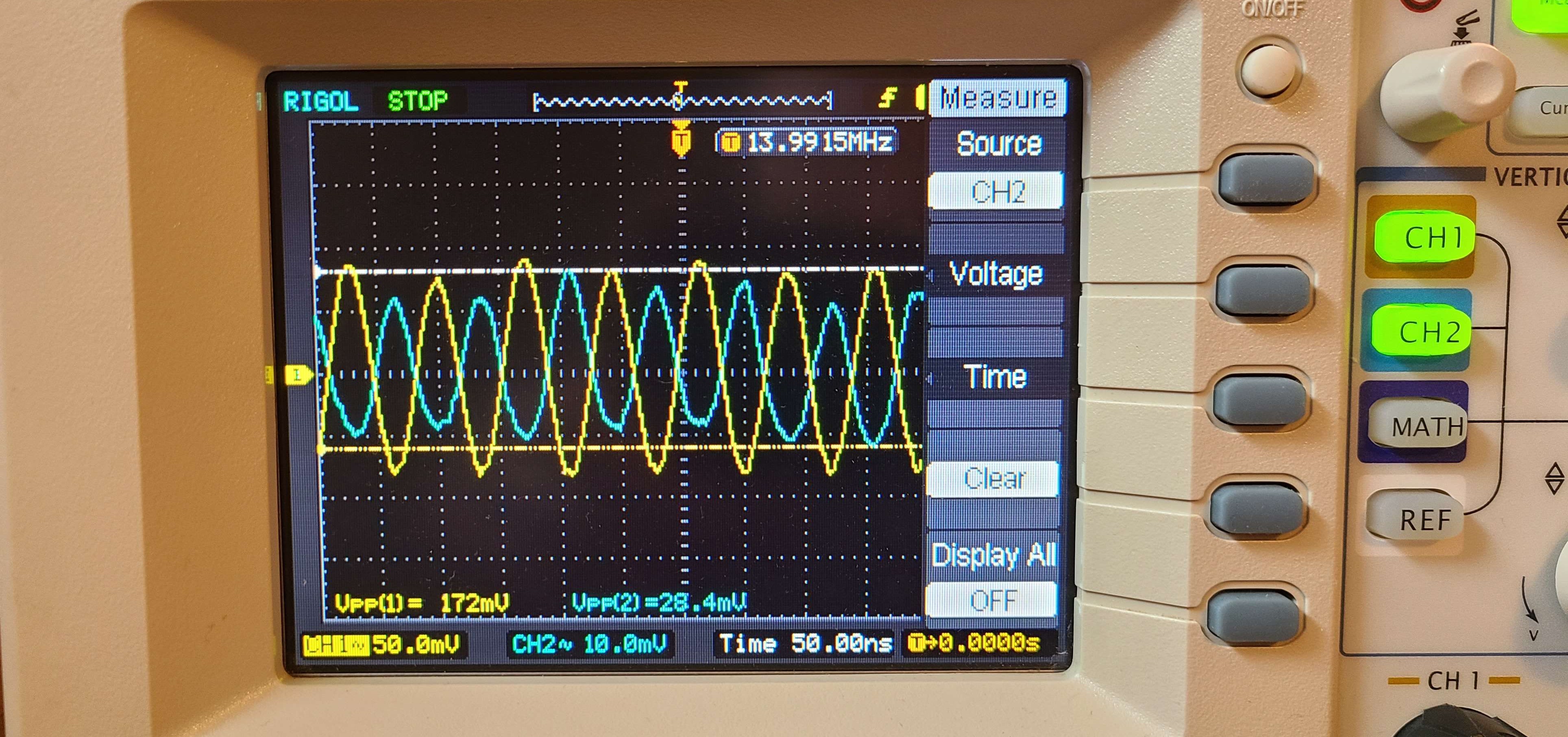
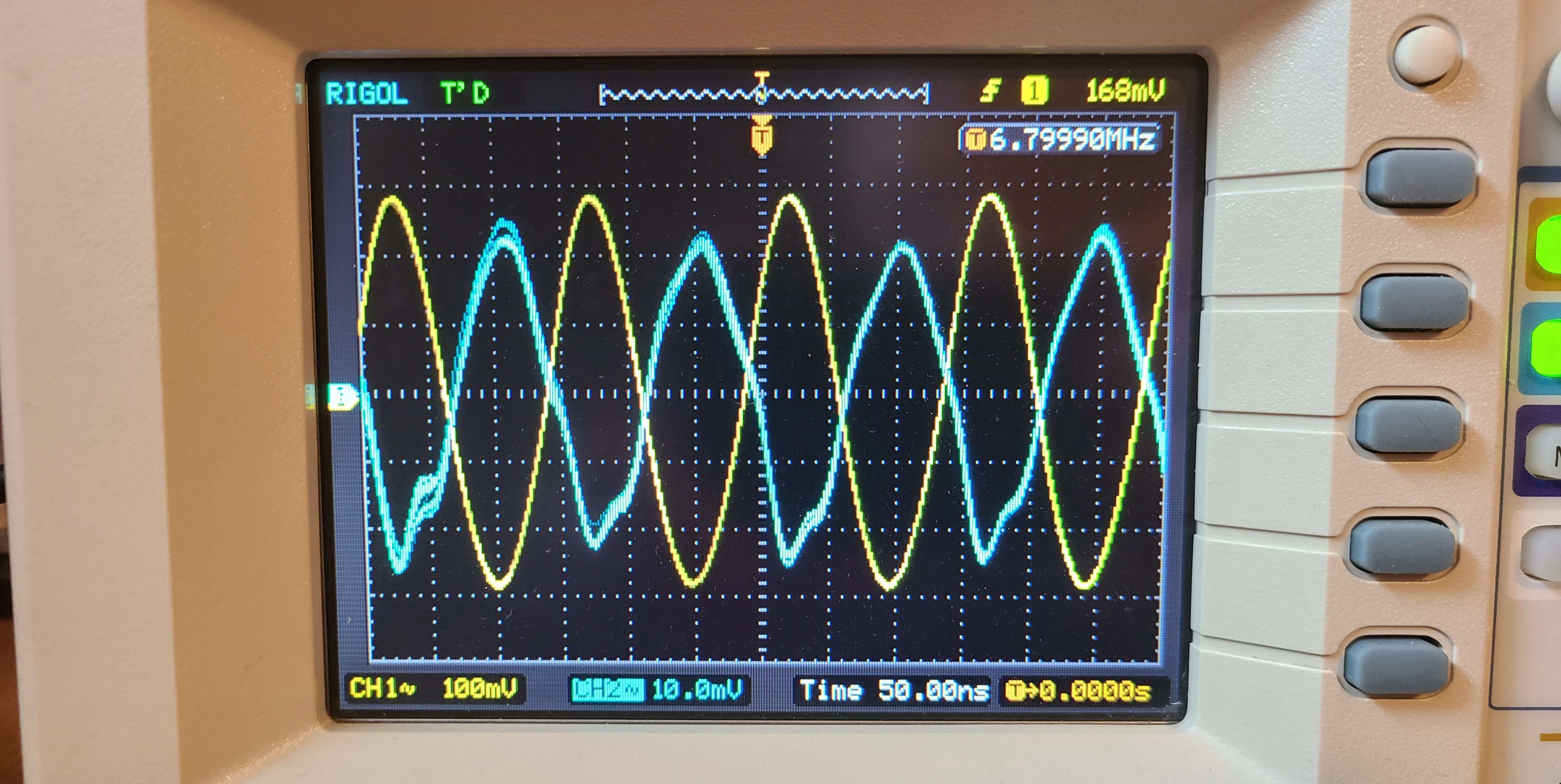
From the results on the oscilloscope, I found the gain to be around 15.8 dB at 14 MHz. A suprise to me though, was that the gain at 7 MHz was 29.5 dB. I suspected this was due to the ferrite mix of the toroids I chose to wind the matching network inductors on. They are miscellanious cores, but I suspect them to be mix 37.
I then connected the amplifier to my NanoVNA to double check the results. Note: I used terminal blocks and RG-58 coaxial for the connections, so there will be some loss there by default.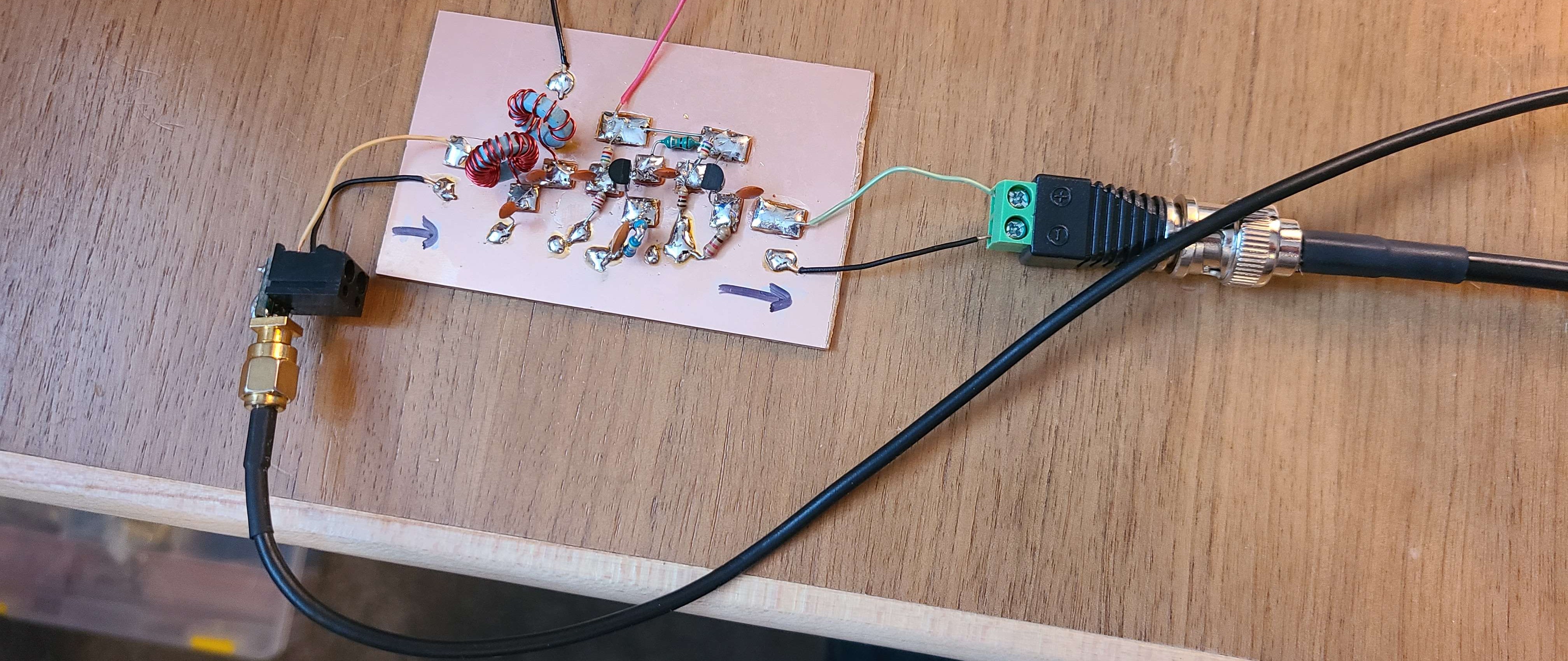
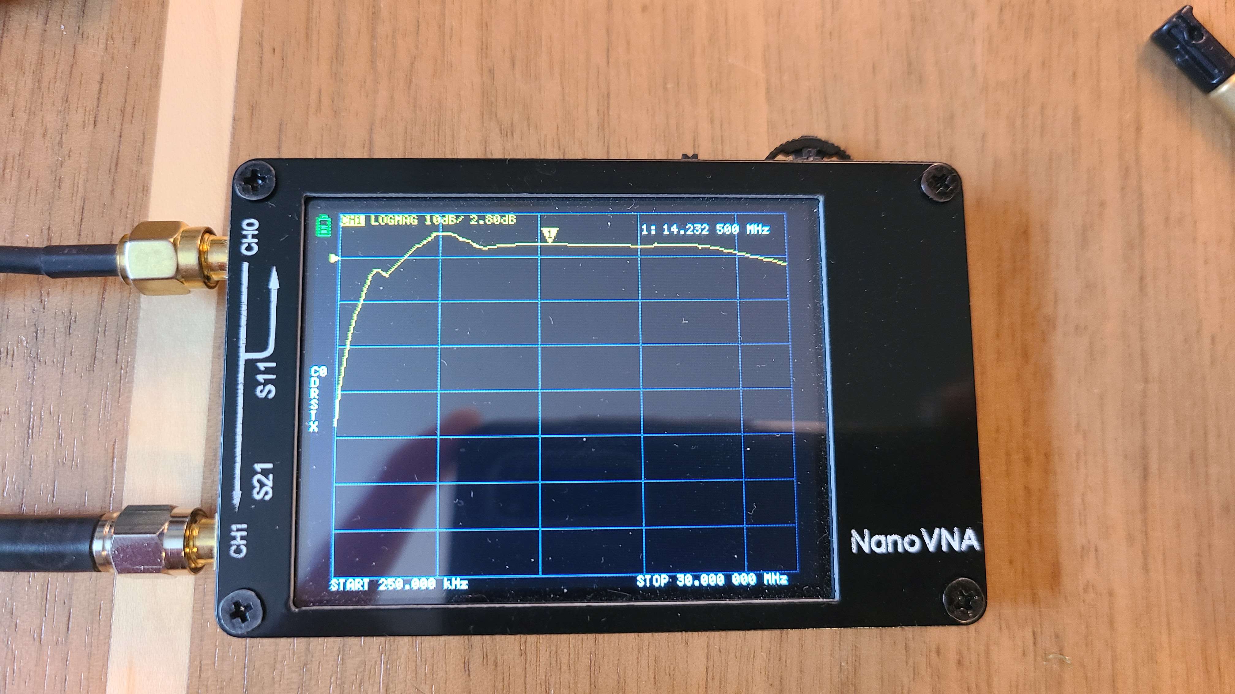
The peak at 7 MHz confirmed the earlier results, and the gain ended up being much less than what was calculated from the oscilloscope measurements. This is likely due to the lossy VNA connections and impedance mismatch at the input and output.
Remarks
I am thinking of changing the input matching network to a simple impedance transformer. I may also look into JFET amplifiers or a cascode configuration.