I recently purchased a Roland Rubix22 USB audio interface second-hand for my PC, and being that it has XLR and 1/4 inch mic jacks, I thought it would be fun to have my hand at making a microphone. While looking into the different types of microphones that exist, I chose to try making a ribbon mic.
Concept
A ribbon mic consists of a very thin light metal ribbon suspended between the poles of a magnet. As the ribbon vibrates due to pressure waves (sounds, voice, etc), a voltage is induced at right angles to both the movement of the ribbon and magnetic field direction. That voltage is then able to be measured and amplified.
Ribbon microphones are also called velocity microphones because the induced voltage is proportional to the velocity of the ribbon and thus of the air particles in the sound wave.
The fully assembled ribbon mic is commonly referred to as a motor, or ribbon mic motor.
This project seemed fairly simple, however there is a lot more to a ribbon mic than meets the eye!
Design & Construction
So first thing is first, I bought some 5mm x 3mm by 25mm long neodynium magnets with a polarity that was through-thickness, meaning the long flat faces are where each pole resides.
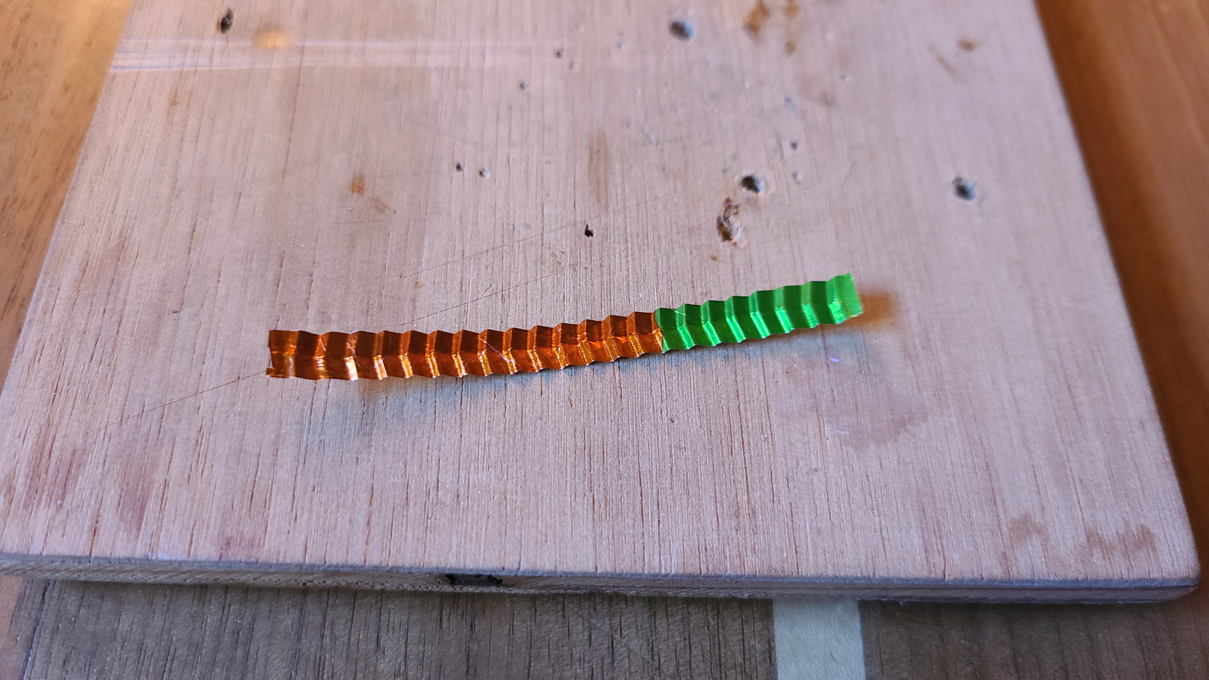
After acquiring the magnets, I turned my focus on the foil. In many ribbon mic designs the ribbon is corrogated to provide some spring tension into the ribbon, which later on allows the mic to be more responsive. I designed a ribbon corrogator to give the aluminum leaf a herringbone style corrogation. The reason I did this was to give the ribbon spring tension in both the long-axis as well as regidity to side-to-side motion.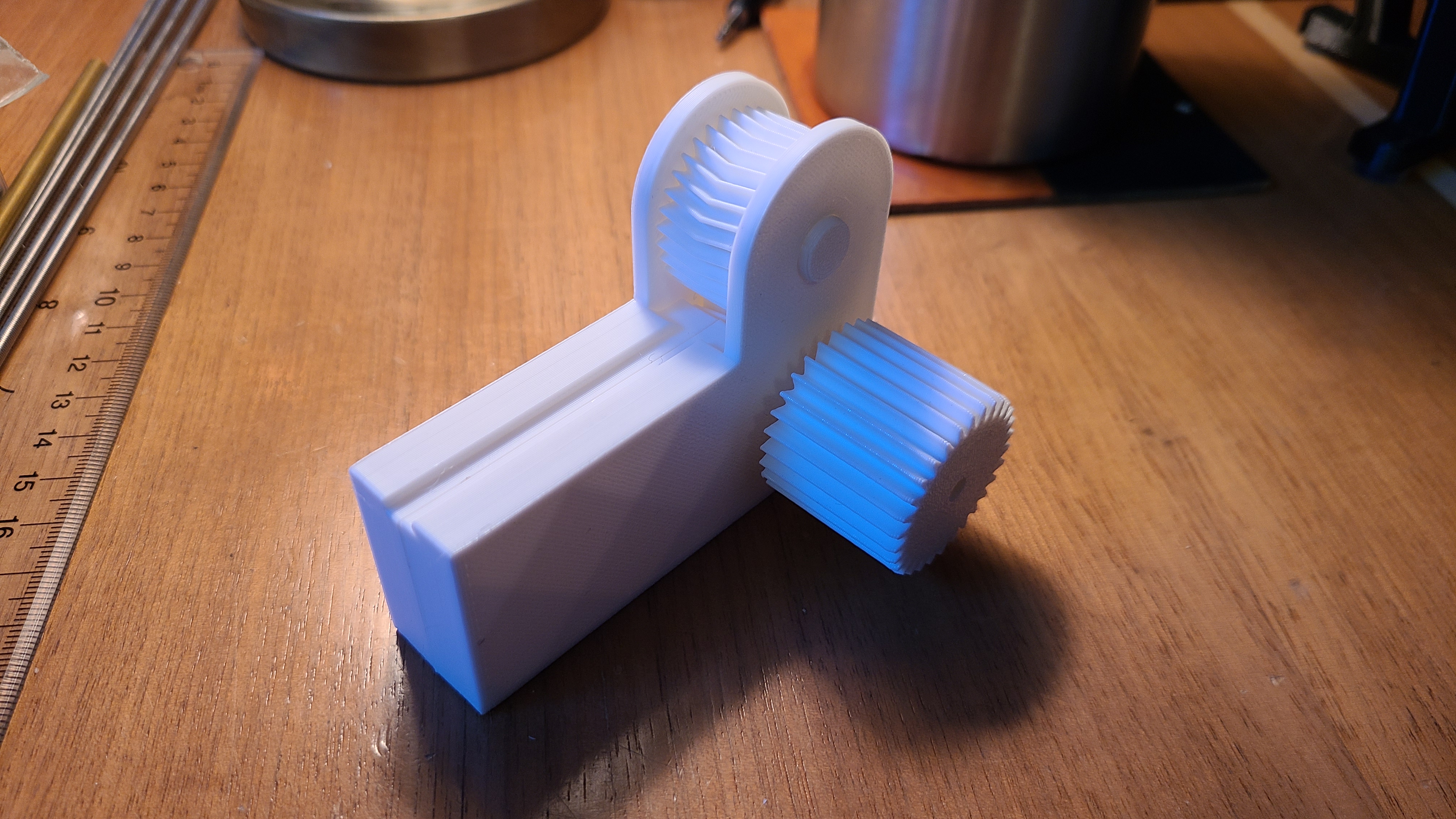
Next up was getting some thin aluminum foil. Normally ribbon mics will have foil that is 6 microns thick (6 micrometers) or smaller. In the theme of doing this on the cheap, I decided to look around for sources of aluminum foil and came across some foil wrapped chocolates. The foil is fairly thin, commonly found to be around 9 and 12 microns, which I believe is suitable.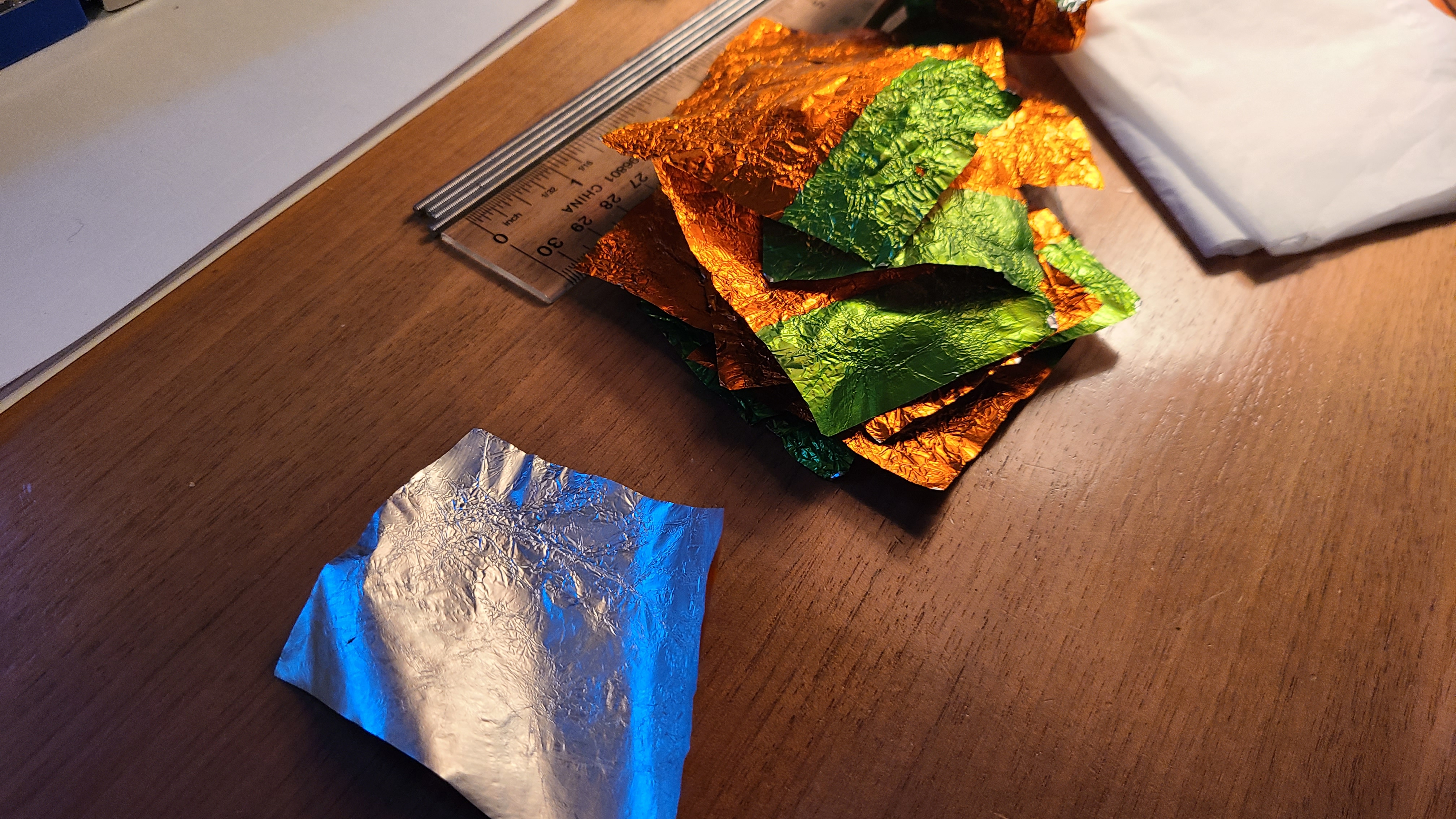
After processing the foil (and consuming the candy) I cut the foil into strips that are 5mm wide and then ran them through the 3D printed corrogator tool.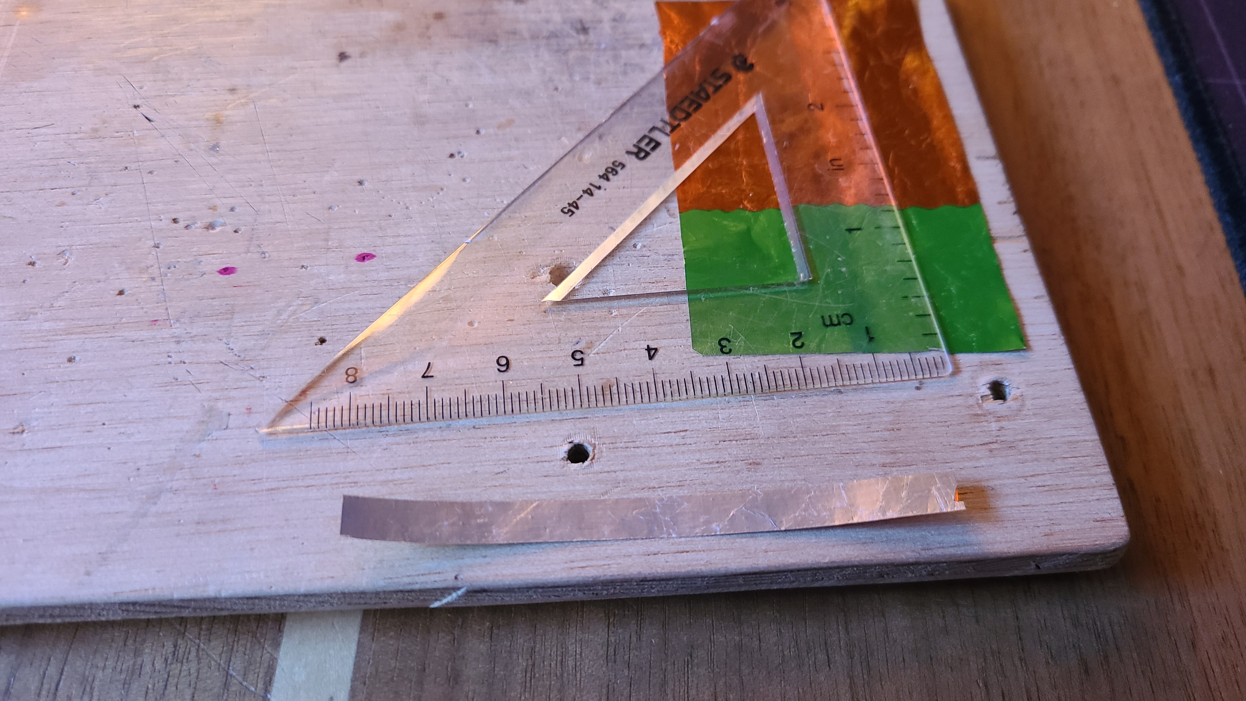
With the ribbon done, I began designing the ribbon mic motor body. As can be seen in the image below, the body holds the magnets apart from each other producing a strong magnetic field within the gap. Between each end of the body are two pieces that will clamp down onto the ribbon, holding it in place.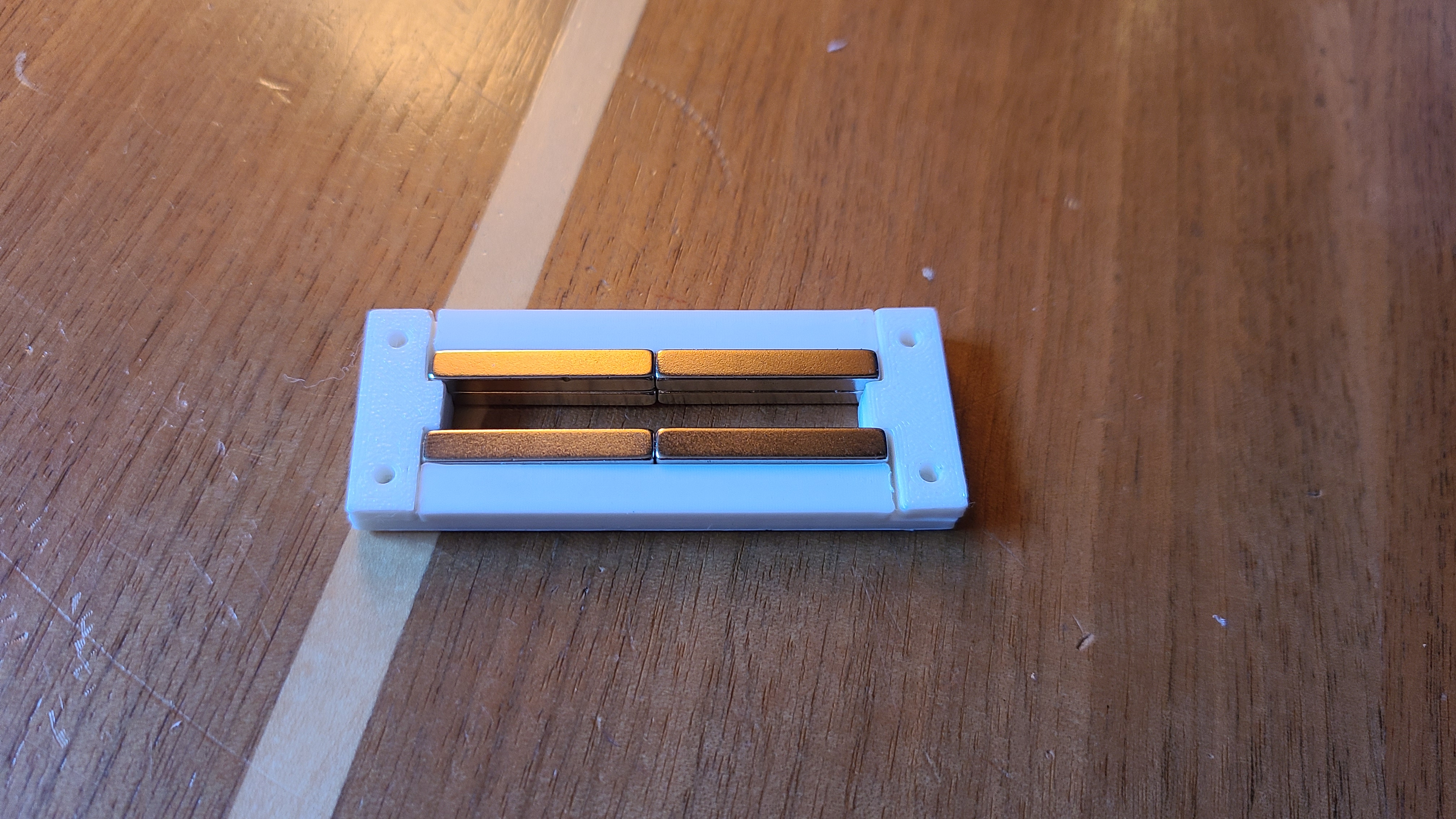
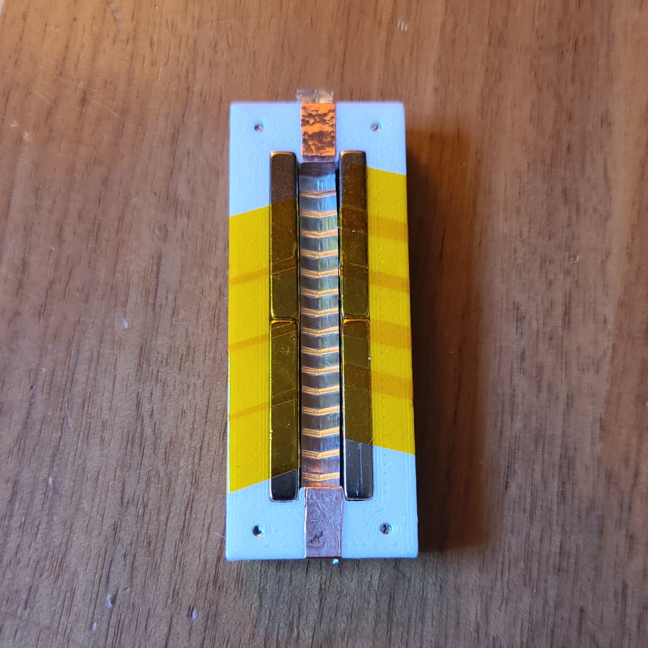
I used copper tape to make the electrical connections at each end of the ribbon, and soldered some wire to each end. When adjusting the tension of the ribbon, I also utilized the lamp I have to visually inspect and ensure the ribbon isn't touching the side walls / magnets. I should also mention I used some kapton tape to further hold the magnets in place.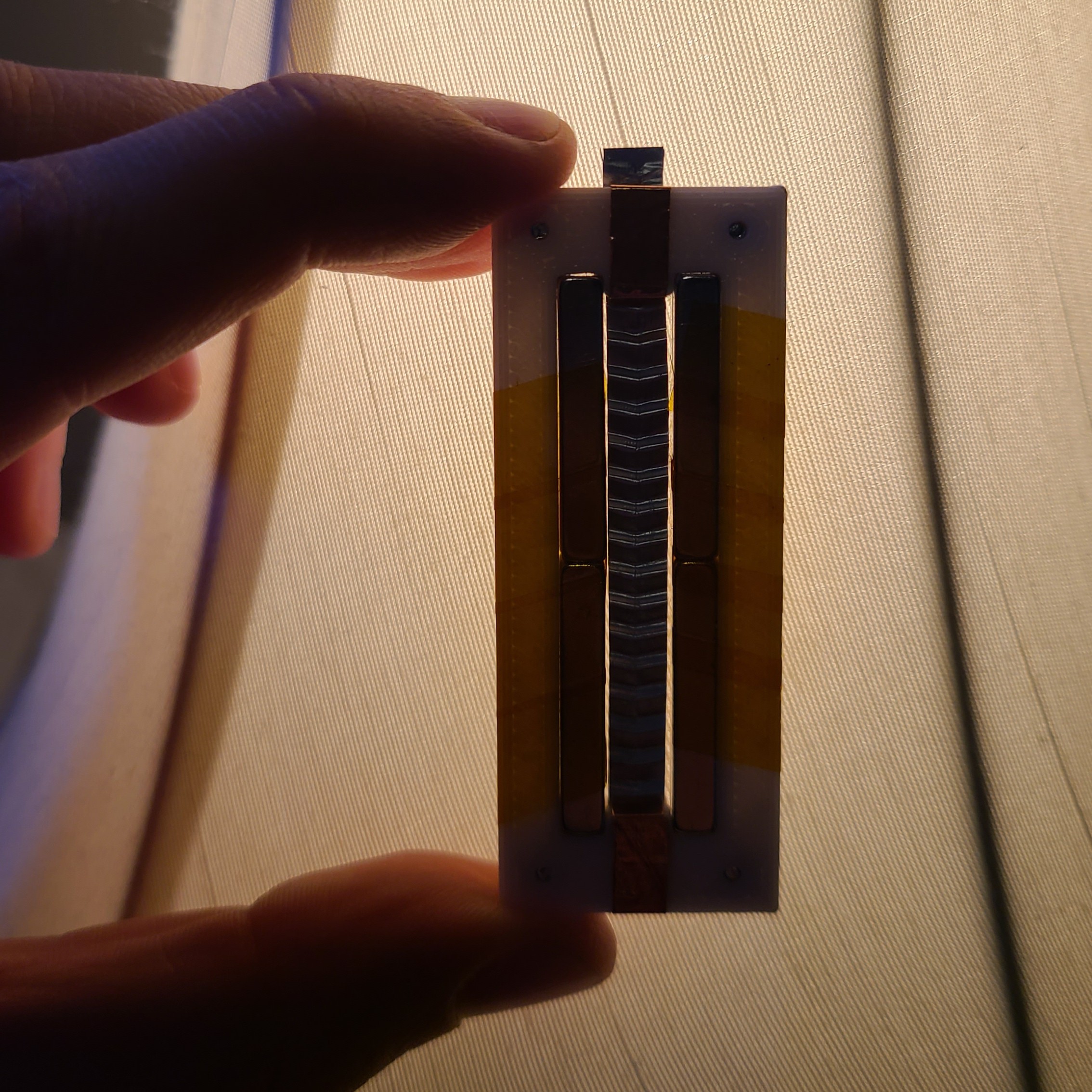
Testing
Because the impedance of a ribbon microphone is extremely low, the impedance has to be increased to get any use out of this mic. This is commonly done via a transformer with a turns ratio of 1:36 to 1:40.
I made my transformer using a T68-2 iron powder toroid, with 6 turns on the primary and 216 turns on the secondary (to achieve a 1:36 turns ratio).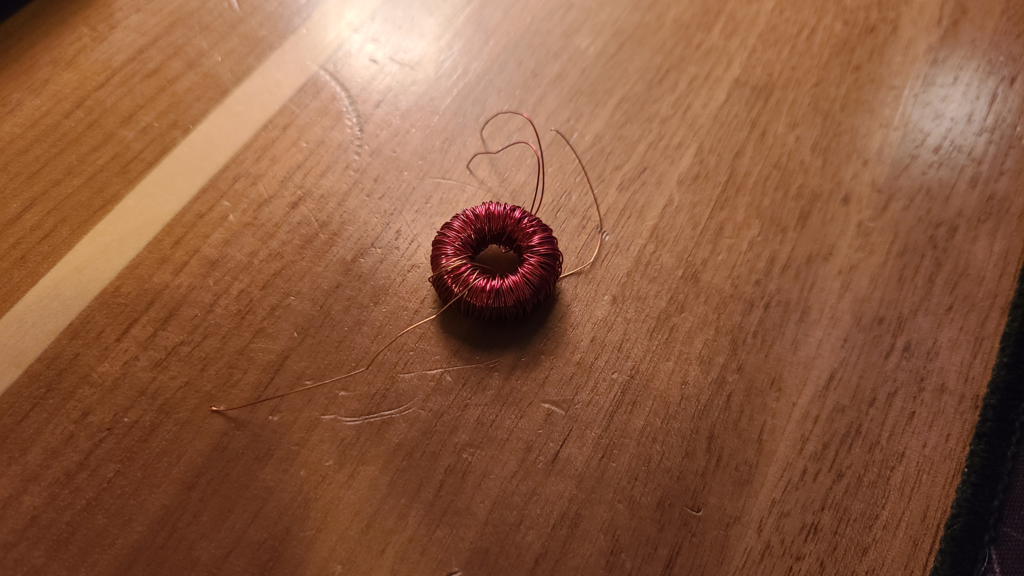
Sadly, I didn't take any photos at the time of the testing I did, as it was rather unsuccessful, so I can't show you the full setup. Plugging the microphone into my audio interface resulted in no audio except for very small blips when I tapped the foil.
Remarks
Overall, I learned quite a bit about ribbon mics in the short time I spent on this project. Maybe some time in the future I will revisit this challenge and succeed.
Some key takeaways that I think may be contributing to the failure:
- Transformer and transformer core were poorly designed, as I used a T67-2 core which is normally low permeability and bad for audio applications.
- Foil may have a non-conductive coating on it from the factory, preventing electrical contact.
- Magnets could be incorrectly oriented.