In an RF receiver, a broad spectrum of signals is present at the input. Because of this, a narrow bandwidth filter is required to pick out only the desired signals. In the case of an amateur radio HF receiver, a bandwidth of 3 kHz is needed to receive single sideband (SSB) transmissions.
Typically, this filtering takes place in the intermediate frequency (IF) portion of a superheterodyne receiver, which usually operates around 6 to 10 MHz. To achieve that narrow of a bandwidth at such a high frequency, high quality (Q) factor resonators are required. Ultimately, the core of the receiver's performance comes down to this IF crystal filter and its ability to isolate the target signal.
Crystal Resonators
This high-Q filter is achievable because of the piezoelectric properties of quartz crystals. When cut to specific dimensions, quartz behaves as a highly stable electrical resonator with a massive Q-factor. By characterizing the crystals, they can be adapted into common bandpass filter topologies, such as Butterworth or Chebyshev filters, to achieve the necessary selectivity.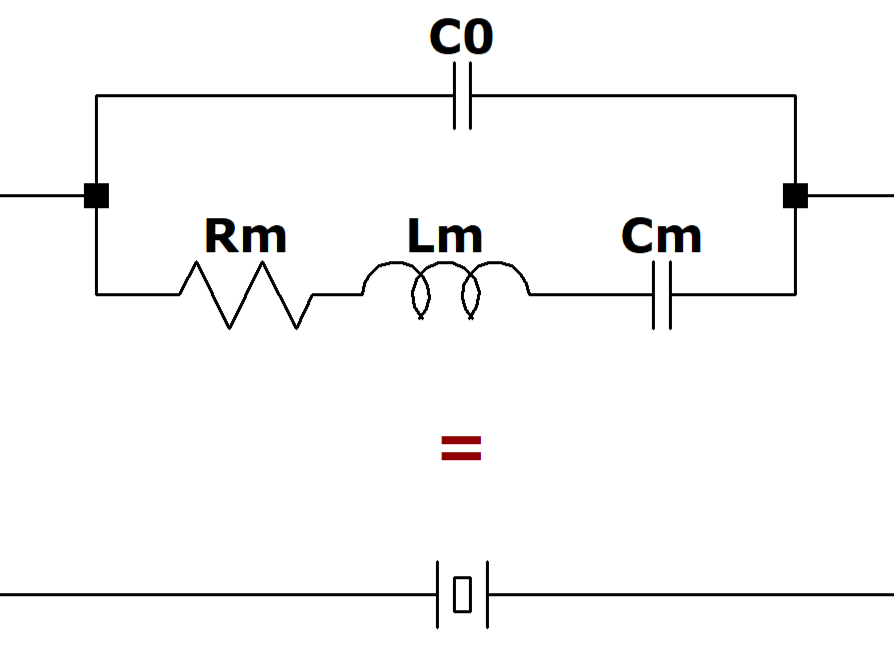
The model above demonstrates how a quartz crystal is electrically characterized. Each component in this equivalent circuit represents one of the crystal's specific motional parameters. By extracting these values, the physical behavior of the quartz is translated into a standard electrical model. This provides a familiar foundation that can be easily simulated and used to design the overall filter.
Modeling the Filter
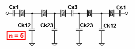
To simplify and speed up the design process I used a software called Dishal by DJ6EV. The Dishal software has mutliple filter types that can be chosen from, but in the case of this filter, I chose a Chebyshev filter topology. Dishal Software The Dishal software is available for download from a number of sources such as changpuak.ch, minikits.com.au, bartelsos.de. Note: if you download using these links, I will take no responsibility for any problems or damages that may occur.
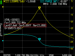
For the Dishal software to properly design the crystal filter I need to provide motional parameters. I measured a batch of 8 MHz microcontroller crystal's and grouped them by frequency. The resulting set I chose to use were centered around 7.998730 MHz.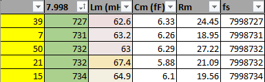
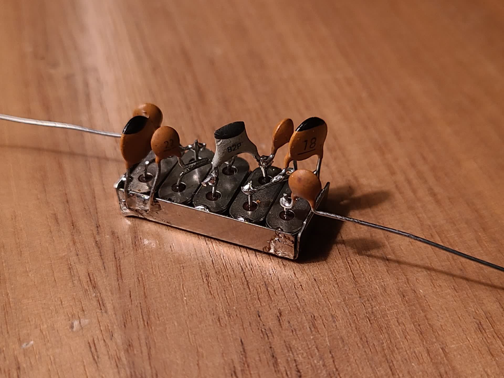
By tweaking the passband ripple I was able to adjust the capacitances enough to get close to standard values. The final values provided by the software were as follows: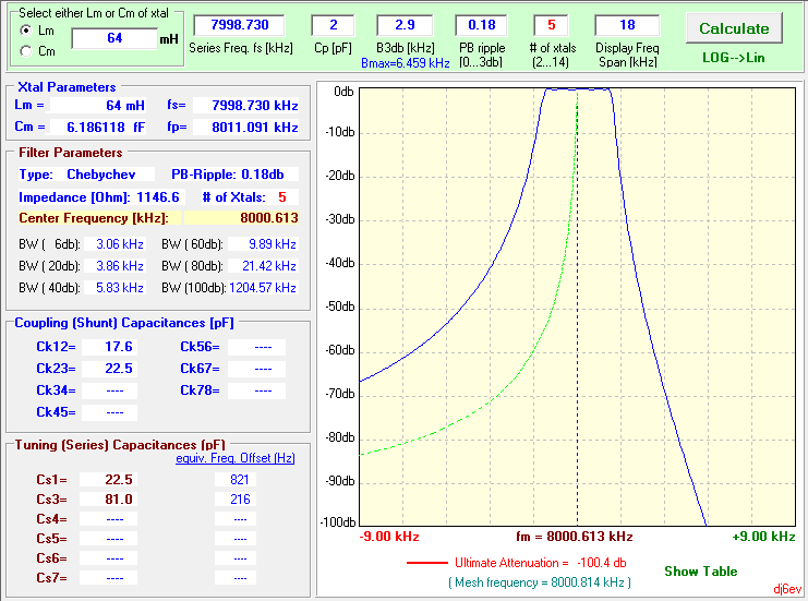
Building the Filter
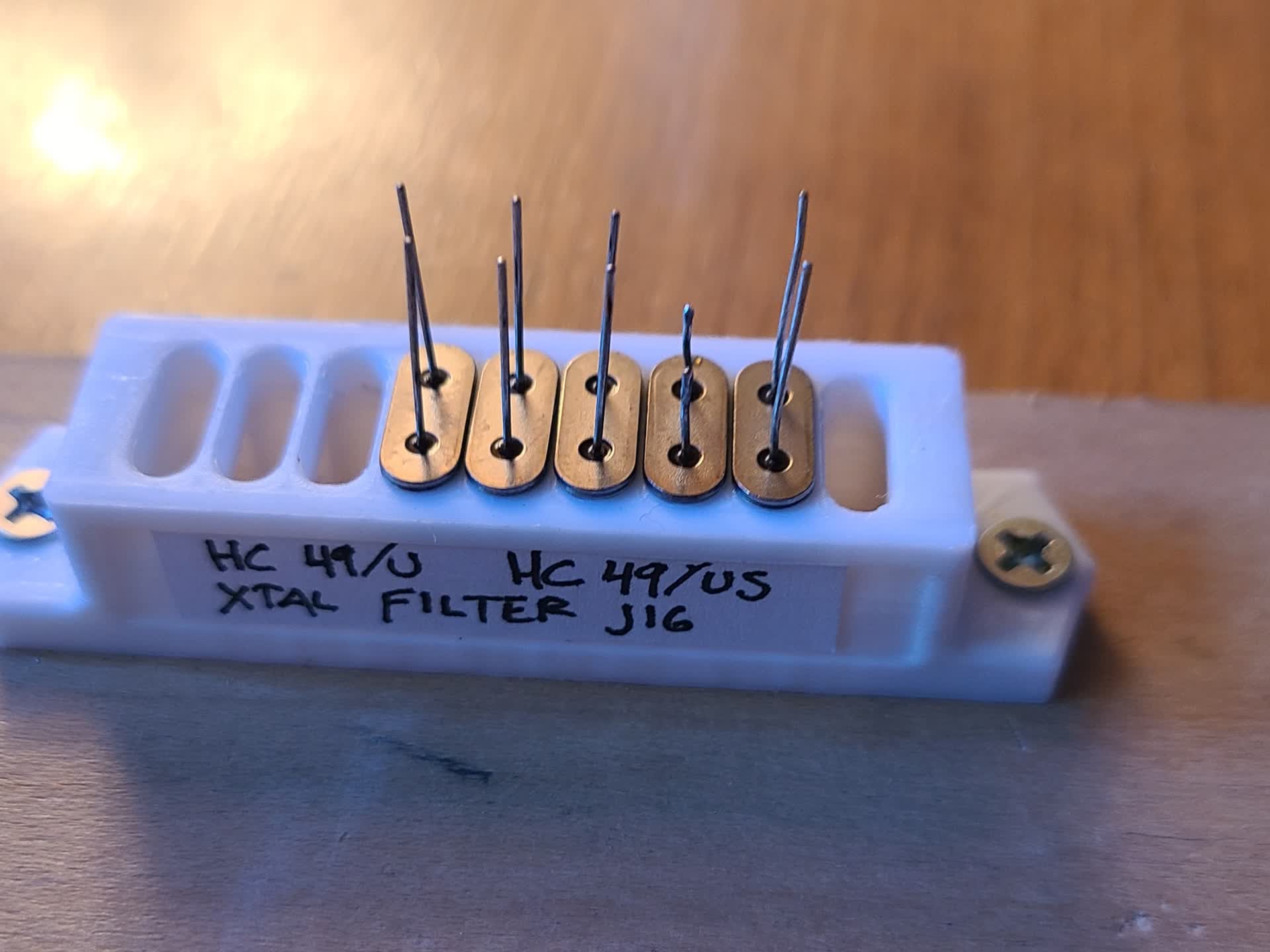
To construct the filter, I placed the crystal's into a 3D printed jig I designed. Then making necessary connections in air, I meticulously assembled the filter. The crystals were then placed in a small enclosure/can and secured.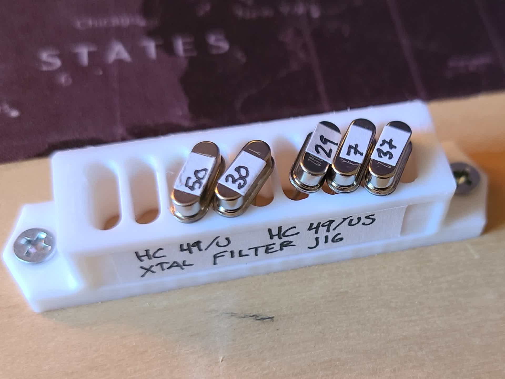
The final filter came out looking better than my previous filter designs.
Testing the Filter
The Dishal software specified an impedance of 1146 Ω, which means I can't simply connect it to the NanoVNA and test it. To test the filter I wound two impedance transformers to convert the 50 Ω system impedance to around 1 kΩ. This was done by winding a 4:18 turns ratio on a Fair-Rite 5943001121 43-mix toroid.
The test setup for measuring the filters passband is shown below.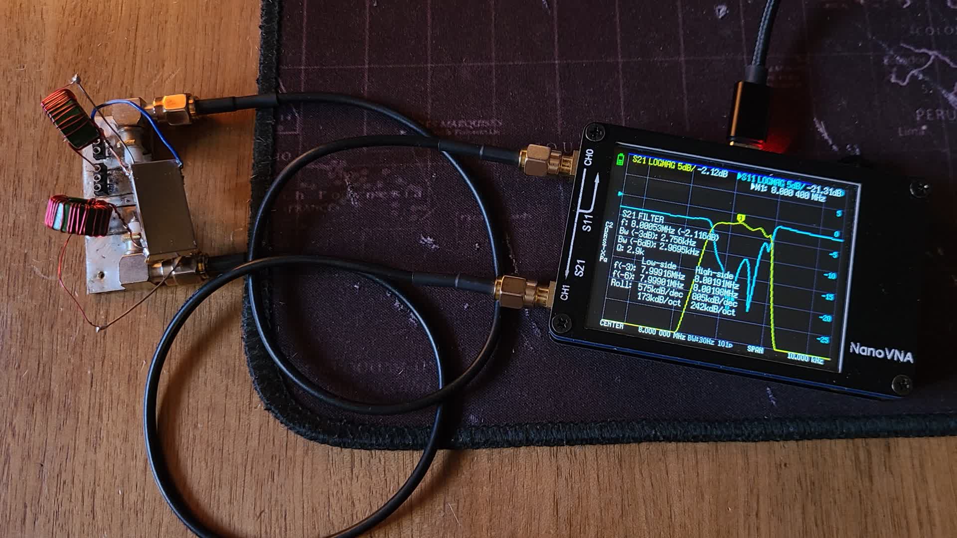
Test Results
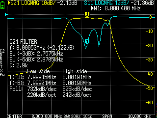
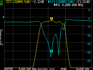
The filter achieved a -3 dB bandwidth of 2.76 kHz, operating between 7.99915 MHz and 8.00191 MHz. It features a low insertion loss of -2.12 dB in the passband and a Q-factor of 2.9k, with very steep skirts on both ends providing the exact selectivity needed for SSB reception.