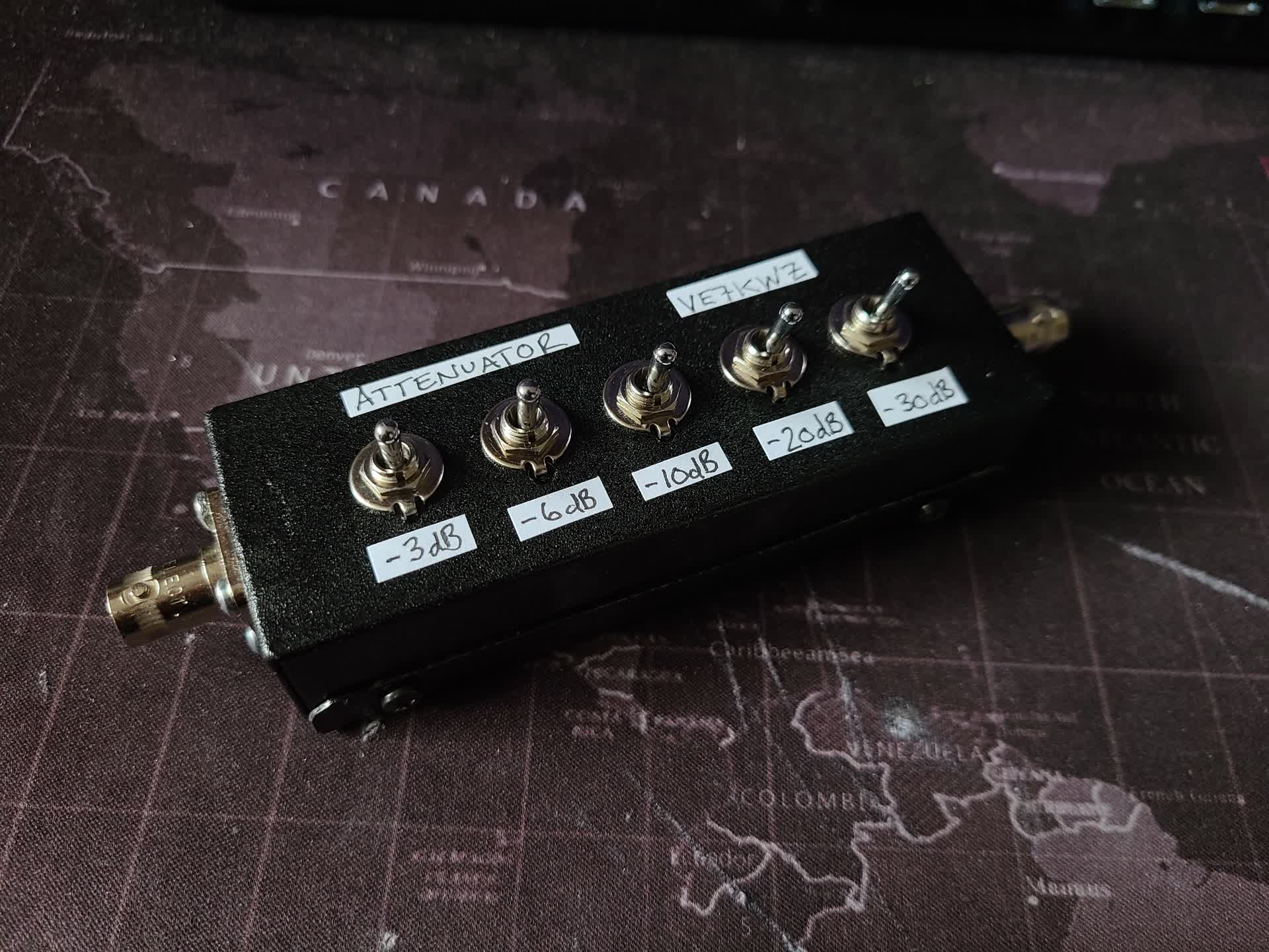
Since I have been testing a number of amplifier designs recently, I needed to be able to attenuate the output of my function generator to a lower level. To accomplish this, I decided to build a switched attenuator box to have some flexibility on the level of attenuation.
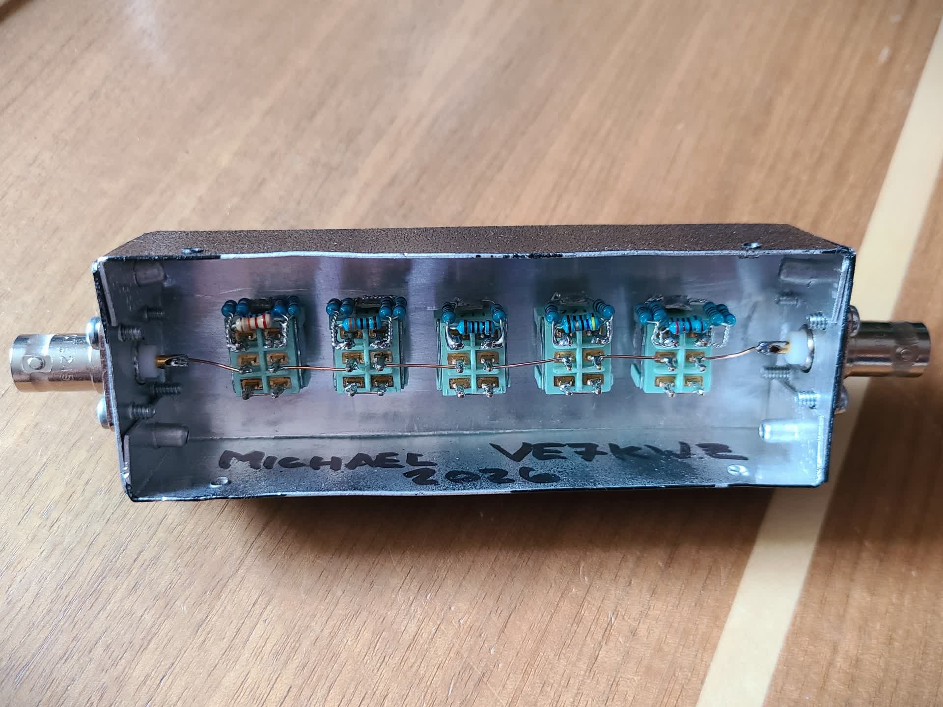
Using double pole double throw (DPDT) switches I made -3 dB, -6 dB, -10 dB, -20 dB, and -30 dB resistive attenuator pads.
Bulding the Attenuators
To build the attenuators, I first calculated the necessary resistor values of each attenuator using the following formulas: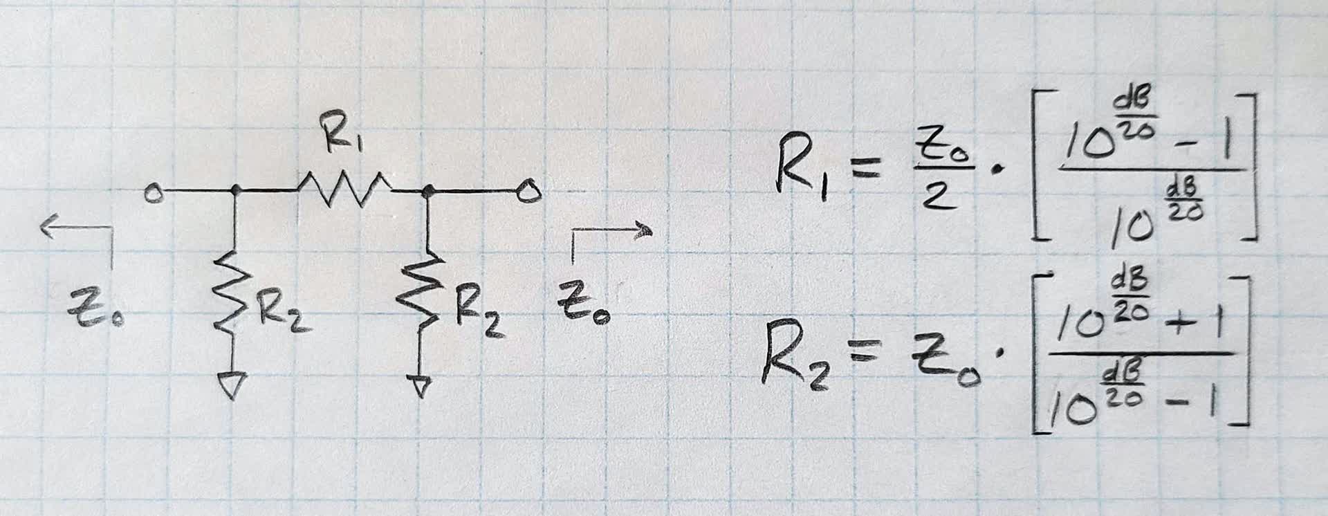
After calculating the resistor values, I built each attenuator using 1/4 watt resistors I had on hand. This meant calculating the best parallel combinations to achieve the oddball resistances needed for most attenuators.
The resulting attenuators were built around the switch using a 1/4 inch eye crimp that I bent around the edge as a ground. This later interacts with the enclosure to connect to the systems ground.
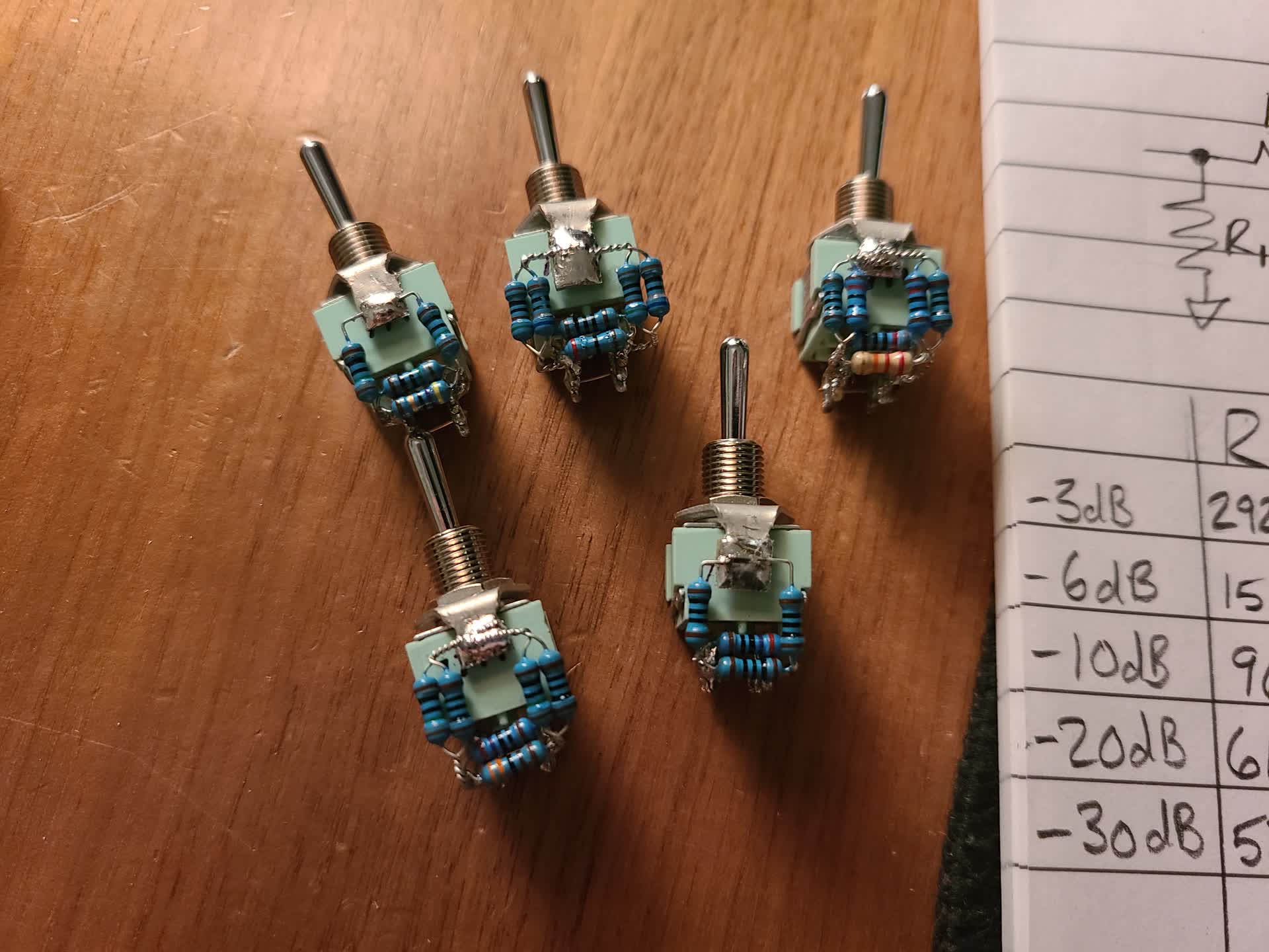
With the attenuators built, next was constructing the enclosure.
Building the Enclosure
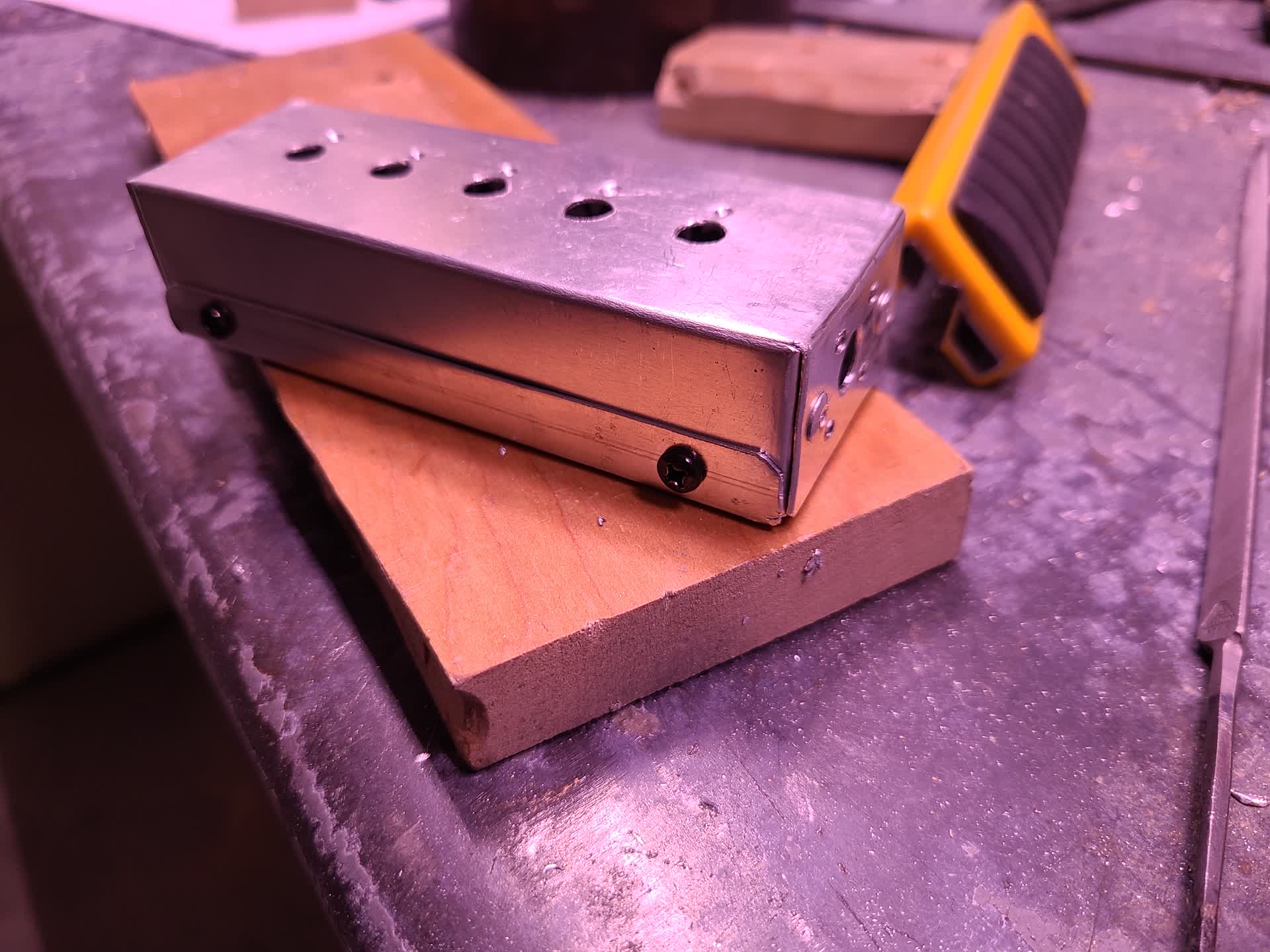
To build the enclosure, I used 18 gauge aluminum sheet and bent it using a combination of shears, wood blocks, a bench vice, and hammer. This method worked quite well considering it is far from precise.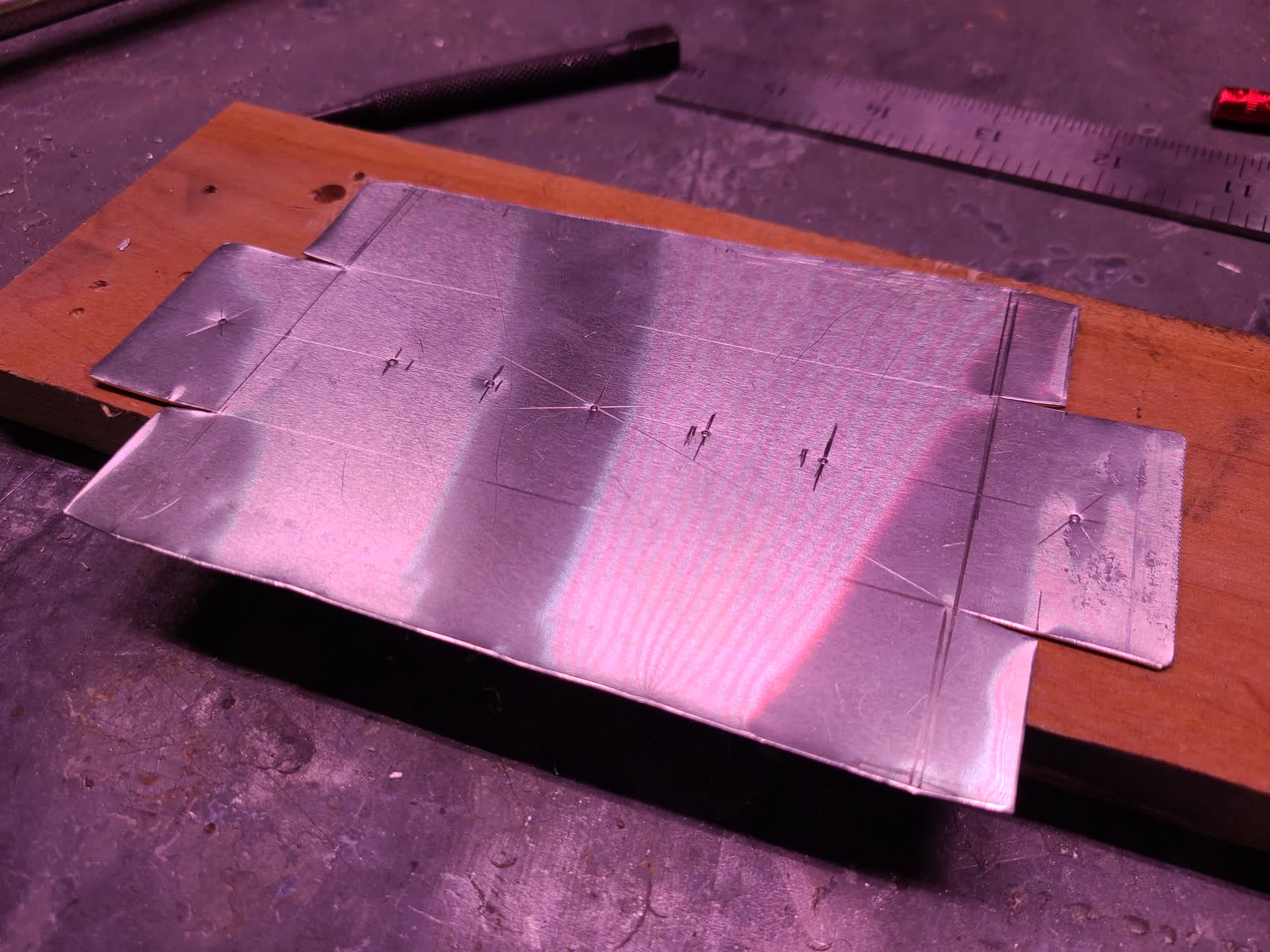
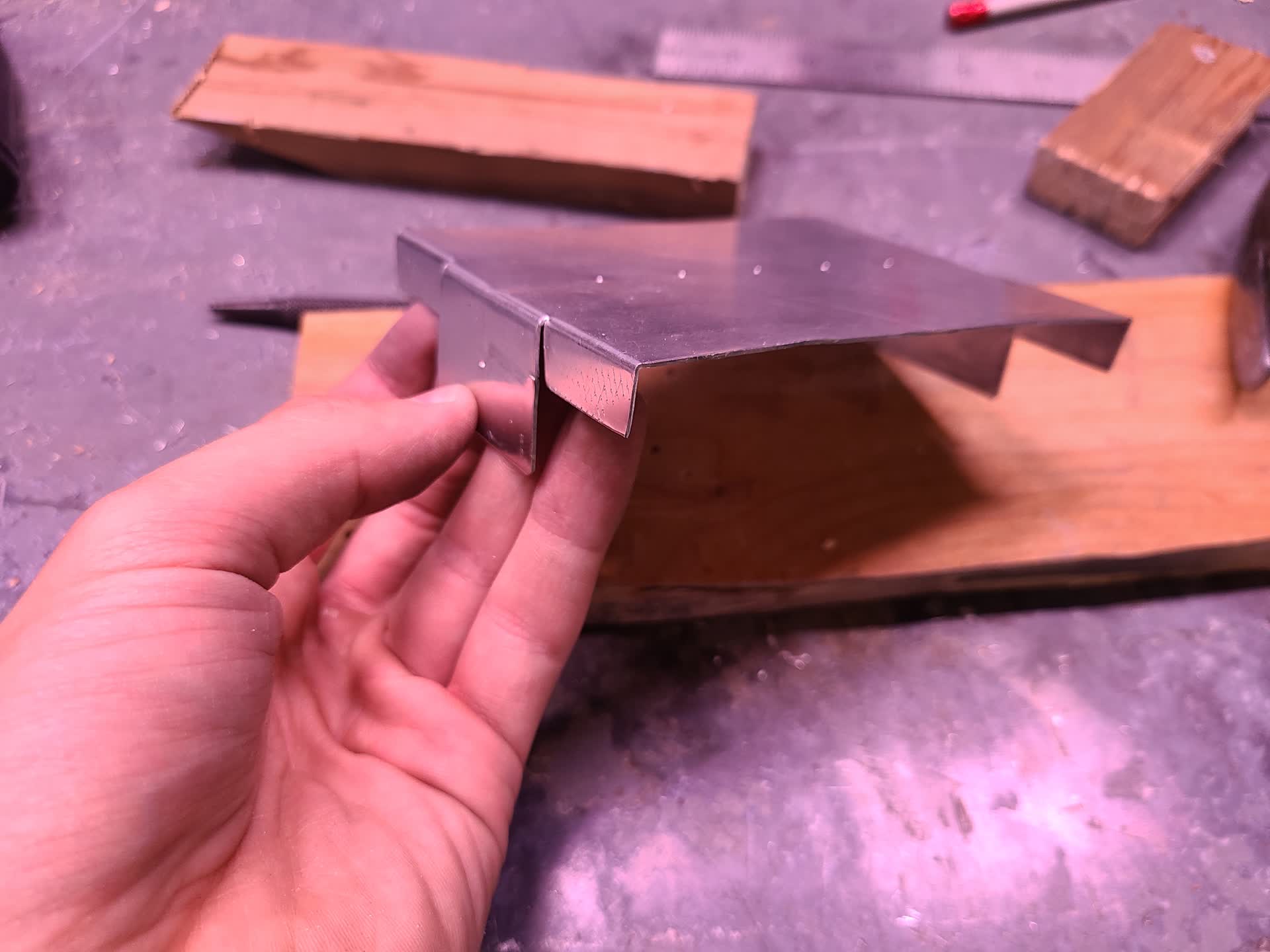
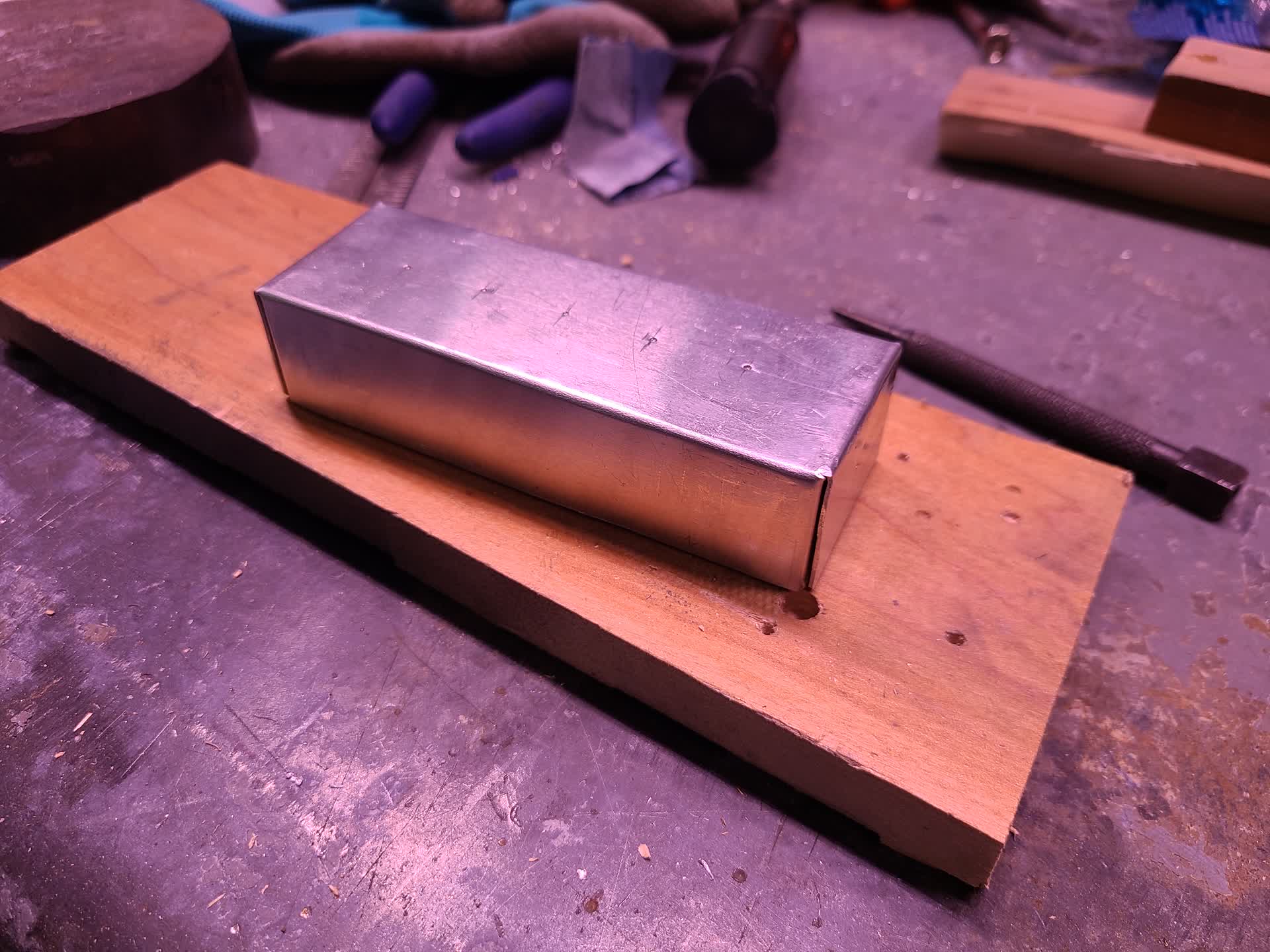
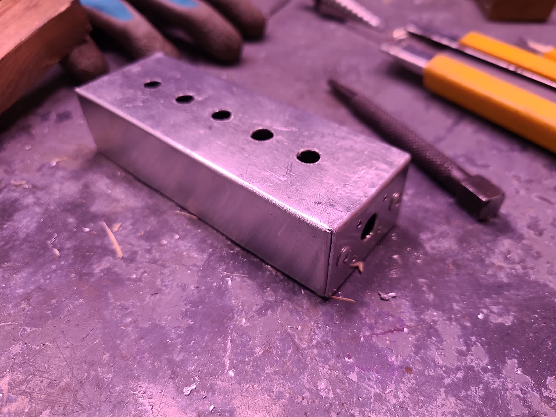
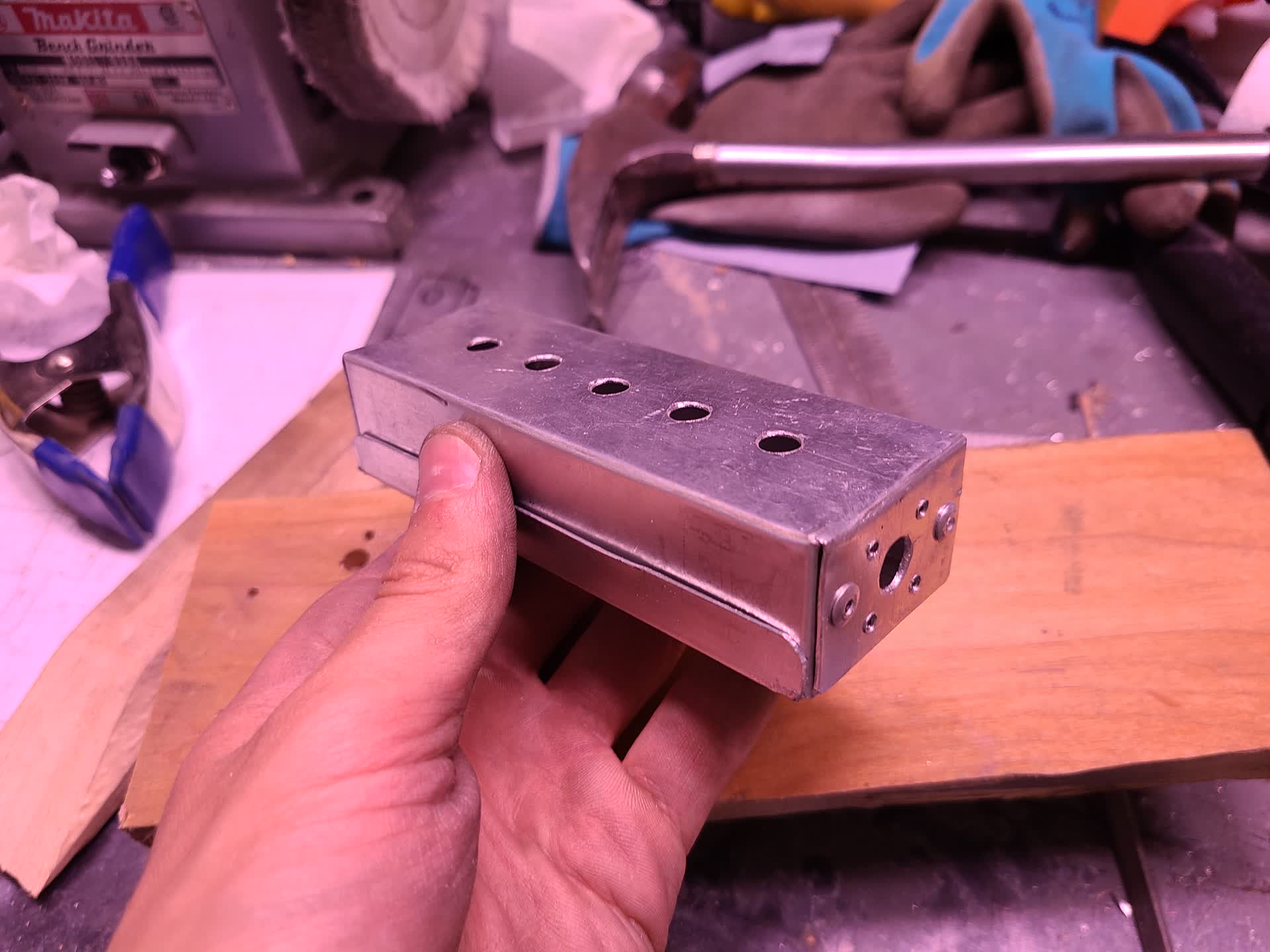
After building the enclosure, I used some truck bed paint to hide the blemishes and give the enclosure a powder coated look.
Assembly
All that was left of this build was to assemble all the parts and make the final solder connections between the switches.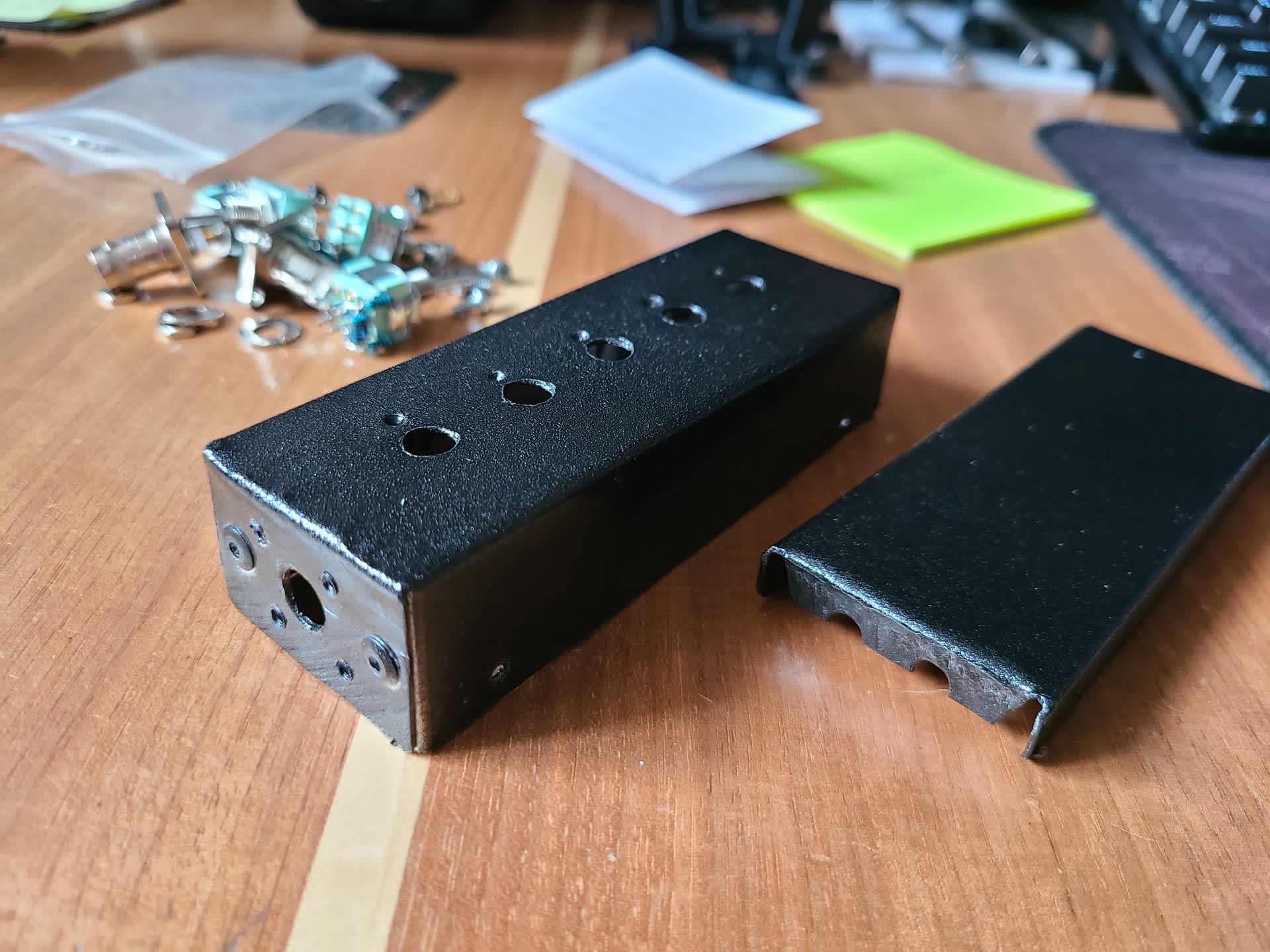
Final Product
The result was a switched attenuator box that I can reliably use up to 30 MHz. Due to the construction of it, parasitics take effect around 50 MHz making it more reactive than resistive. I plan to make a VHF/UHF attenuator box using a dedicated PCB in the future.