Continuing along with my HF superheterodyne receiver project, I designed and tested a tuned IF amplifier to feed the crystal filter. The tuned IF amplifier determines the receiver's ultimate performance by providing stable, high-gain amplification and precise bandpass filtering.
Because these stages operate at a fixed frequency (8 MHz in my case), they allow for the use of high-Q tuned circuits that maintain consistent selectivity regardless of the original signal's carrier frequency. Mastering the design and alignment of these tuned circuits is essential for maximizing sensitivity and eliminating adjacent channel interference.
Design and Simulation of the Amplifier
The design of this amplifier followed the same process as all the other cascode amplifiers I made so far. I first set the DC bias around a desired collector current. In this case I chose 5 mA to achieve lower nosie while still having plenty of amplification headroom.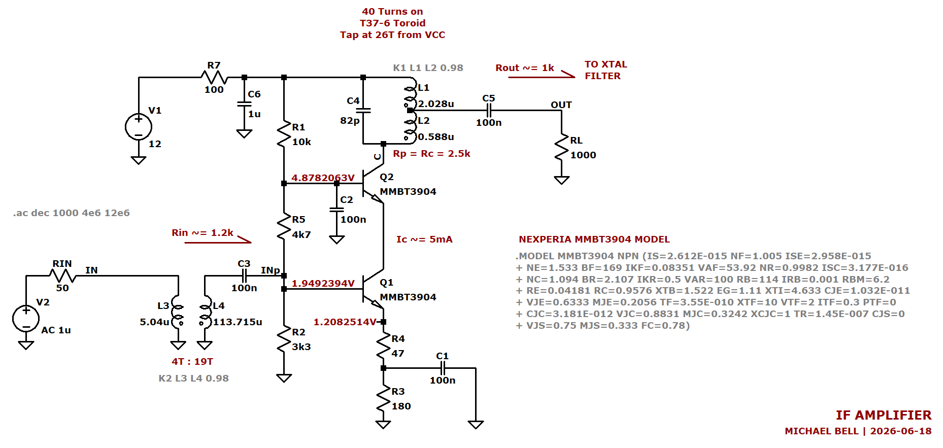
The key difference in the design of this amplifier was adding a tuned LC tank circuit for 8 MHz at the output providing a parallel load to the amplifier of 2.5 kΩ. I tuned this tank to have a loaded Q of around 8.
A broadband transformer was used to match the input 1.2 kΩ of the amplifier to the 50 Ω system.
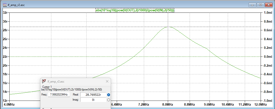
After running the simulation, the input impedance was confirmed to be around 50 Ω, and the power gain to be around 28 dB. The simulation gain was slightly higher than I was aiming for, but I also didn't account for losses within each component.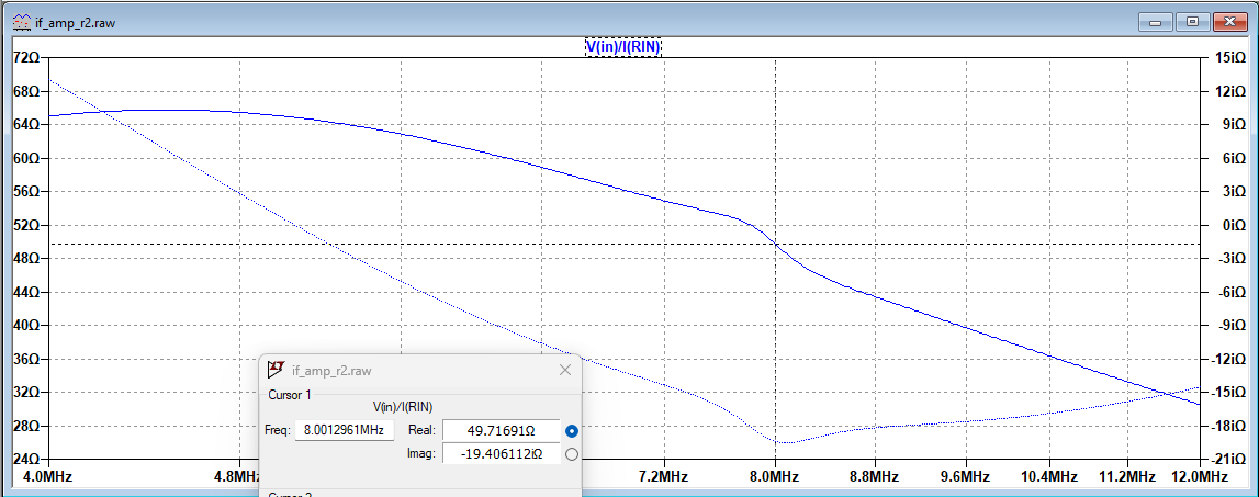
PCB Fabrication
With the simulation complete, I designed a PCB for the amplifier in KiCAD.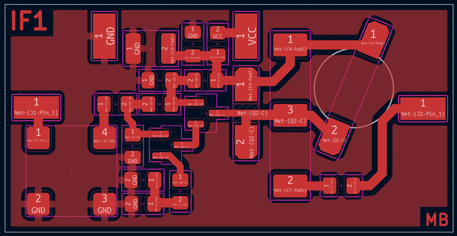
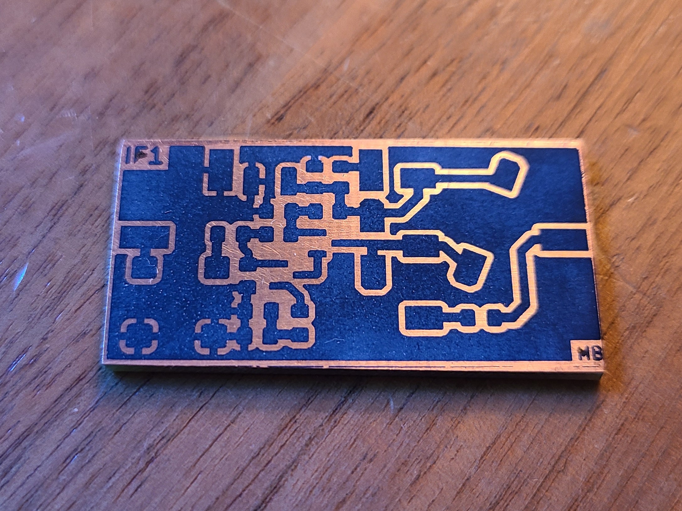
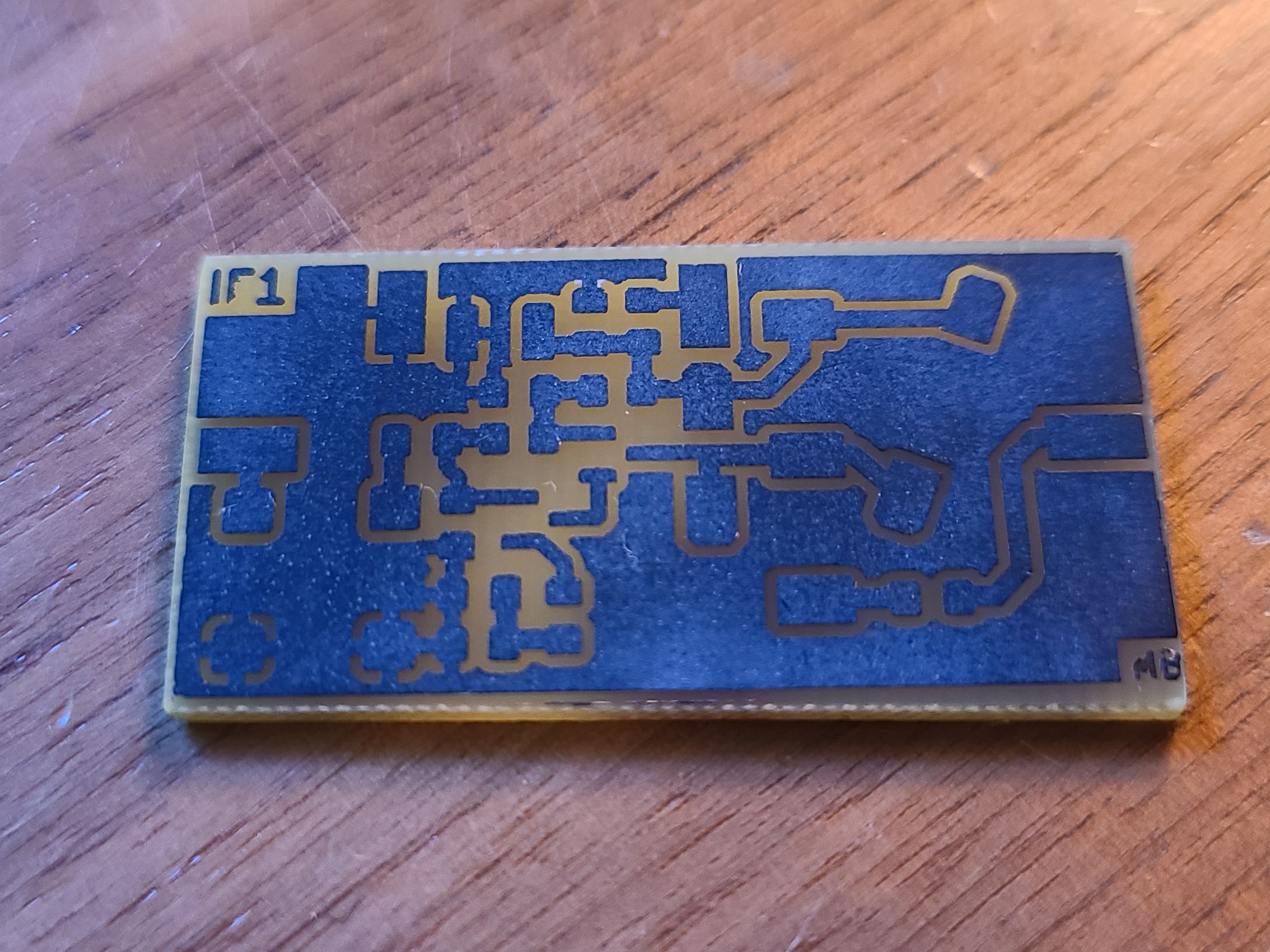
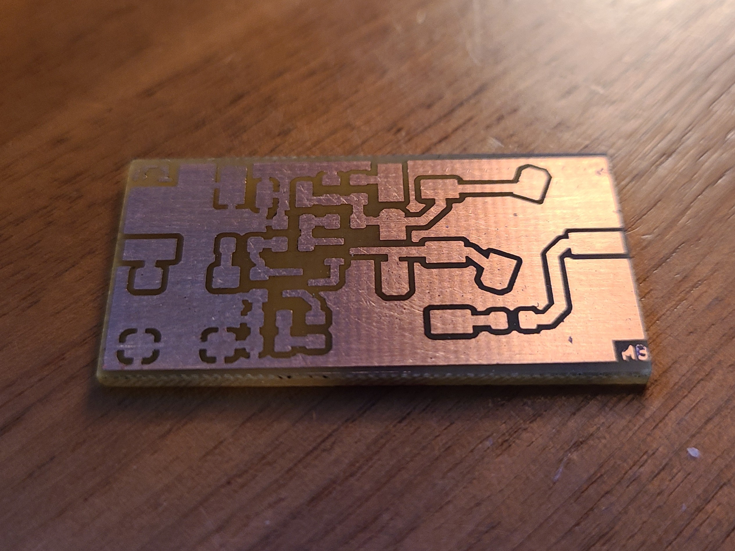
With the layout complete, I then used the toner transfer method to mask a copper clad board for etching. I etch using ferric chloride etchant.
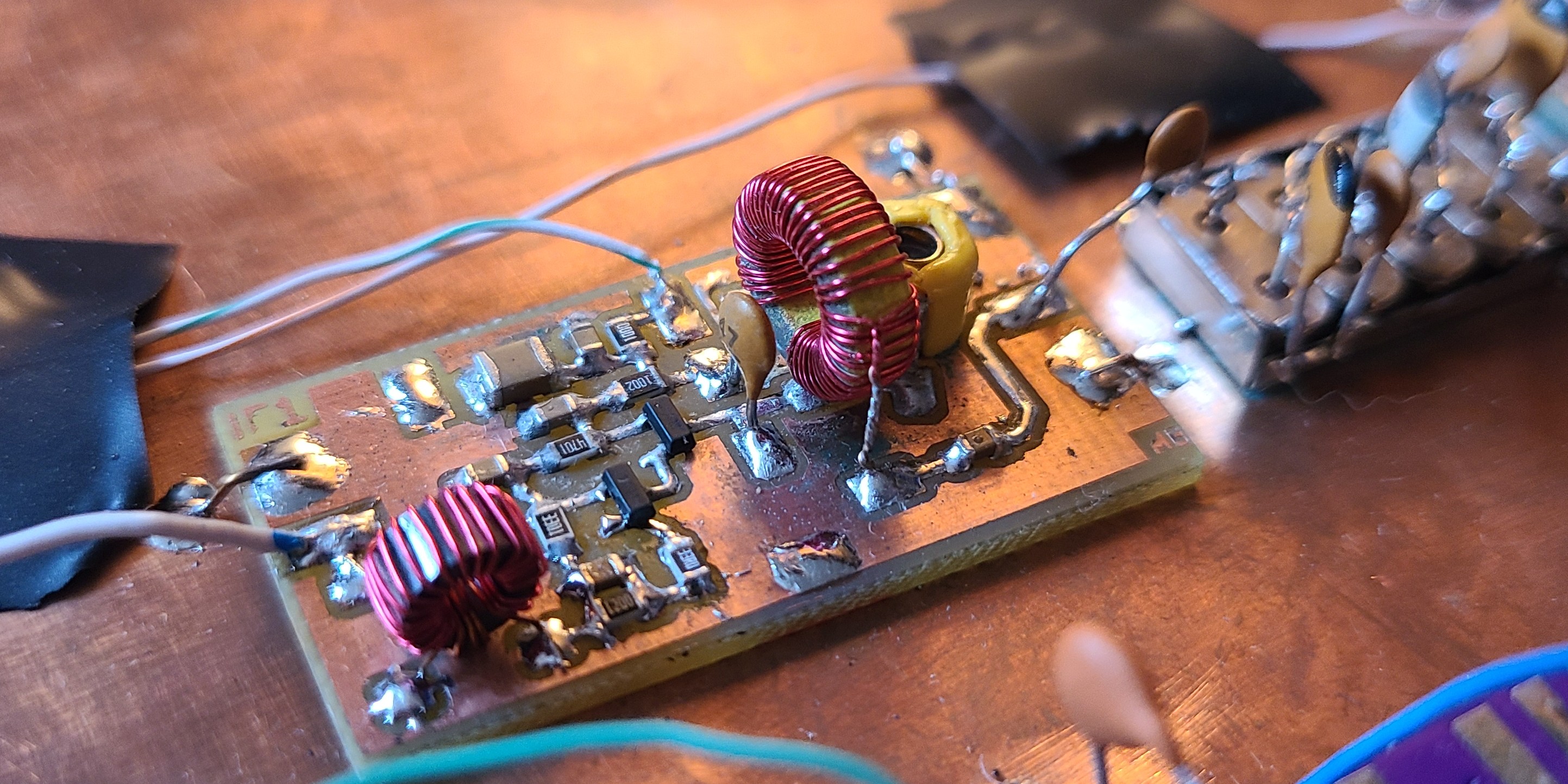
Amplifier Assembly
Using parts I have on hand I soldered together the amplifier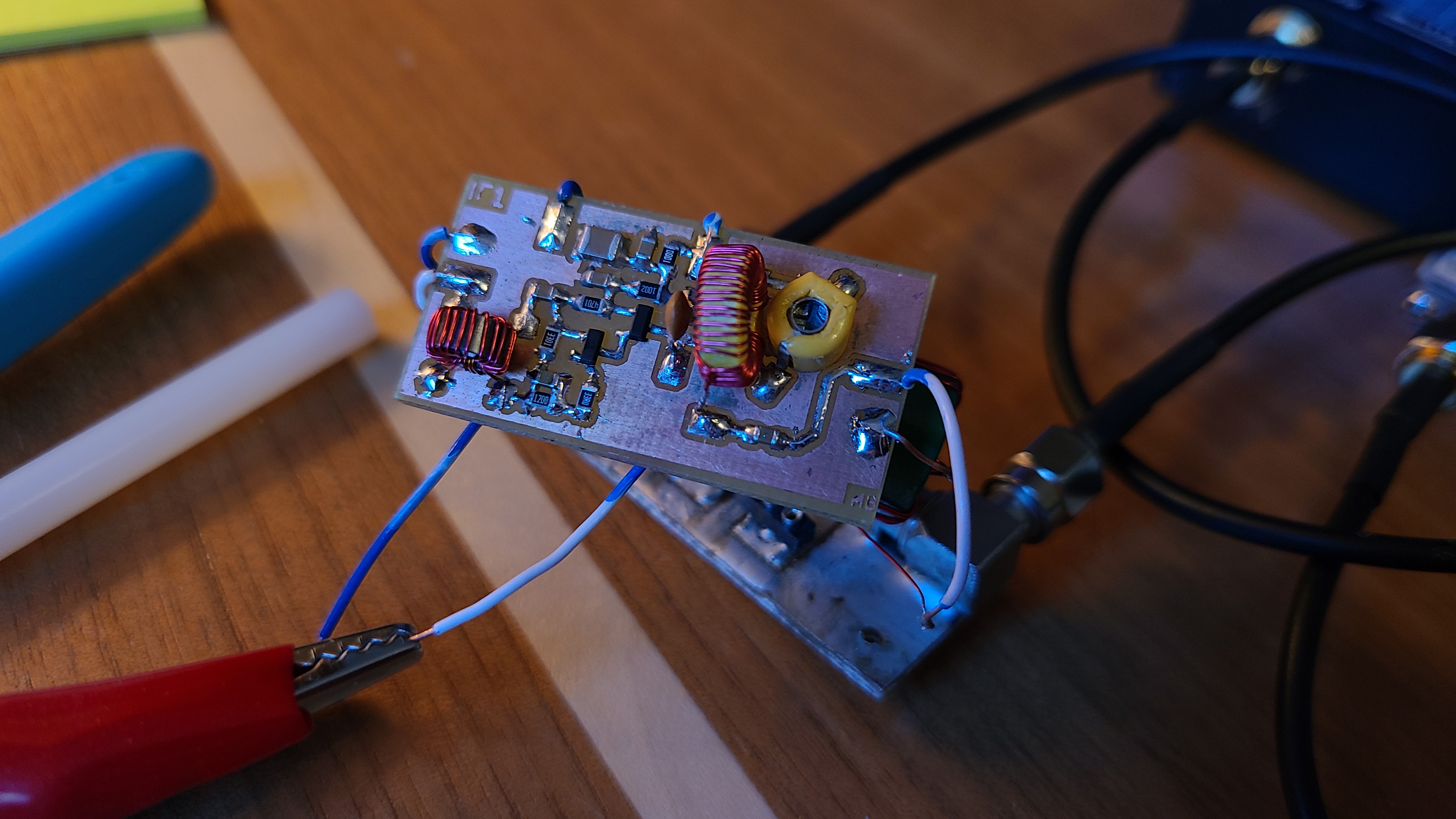
Note on Emitter Resistor Values
During testing, I decided to change the emitter resistor values. I changed the 47 Ω resistor to 33 Ω, and the 180 Ω resistor to 120 Ω. This was in an effort to increase the gain slightly.
Winding the tuned tanks Inductor
To wind the inductor, I used an FT37-6 as it is great for high-Q inductors at 8 MHz. The FT37-6 has an $A_L$ of 3 $nH/Turn^2$. This meant I needed 40 turns to achieve the 4.8 uH of inductance needed for the tuned LC tank.
Additionally, I wanted to drive a 1 kΩ load (the crystal filter) with this amplifier, so I needed to tap the inductor at a specific turn. This was equivalent to calculating the tap on an autotransformer.
The tap position was found by first calculating the turns ratio $\sqrt{2500/1000} = 1.58$ then using that, I calculate the number of turns before the tap $N_{tap} = 40/1.58 = 25.38$ I rounded this up to 26 turns. This meant, from Vcc, I have 26 turns, then a tap, then 14 more turns.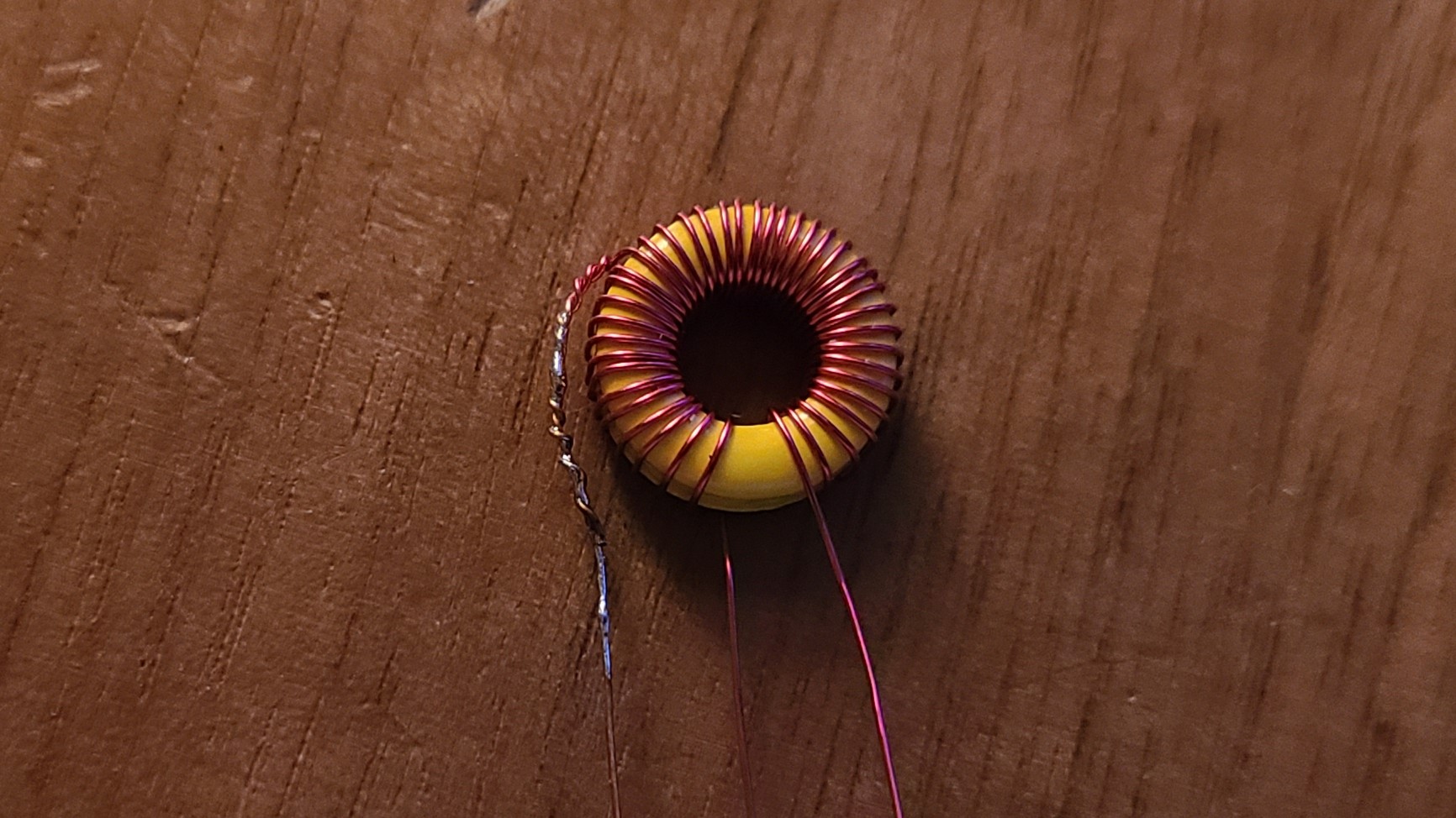
Testing the Amplifier
To test the amplifier, I used my test jig with my NanoVNA. On the transmission (S21) port, I added a 20 dB attenuator to protect the VNA.
For the 1 kΩ output impedance, I included a broadband transformer using a 4:18 turn ratio on a 43 mix toroid ($A_L = 480 nH/Turn^2$). This could add some insertion loss, so the gain could possibly be higher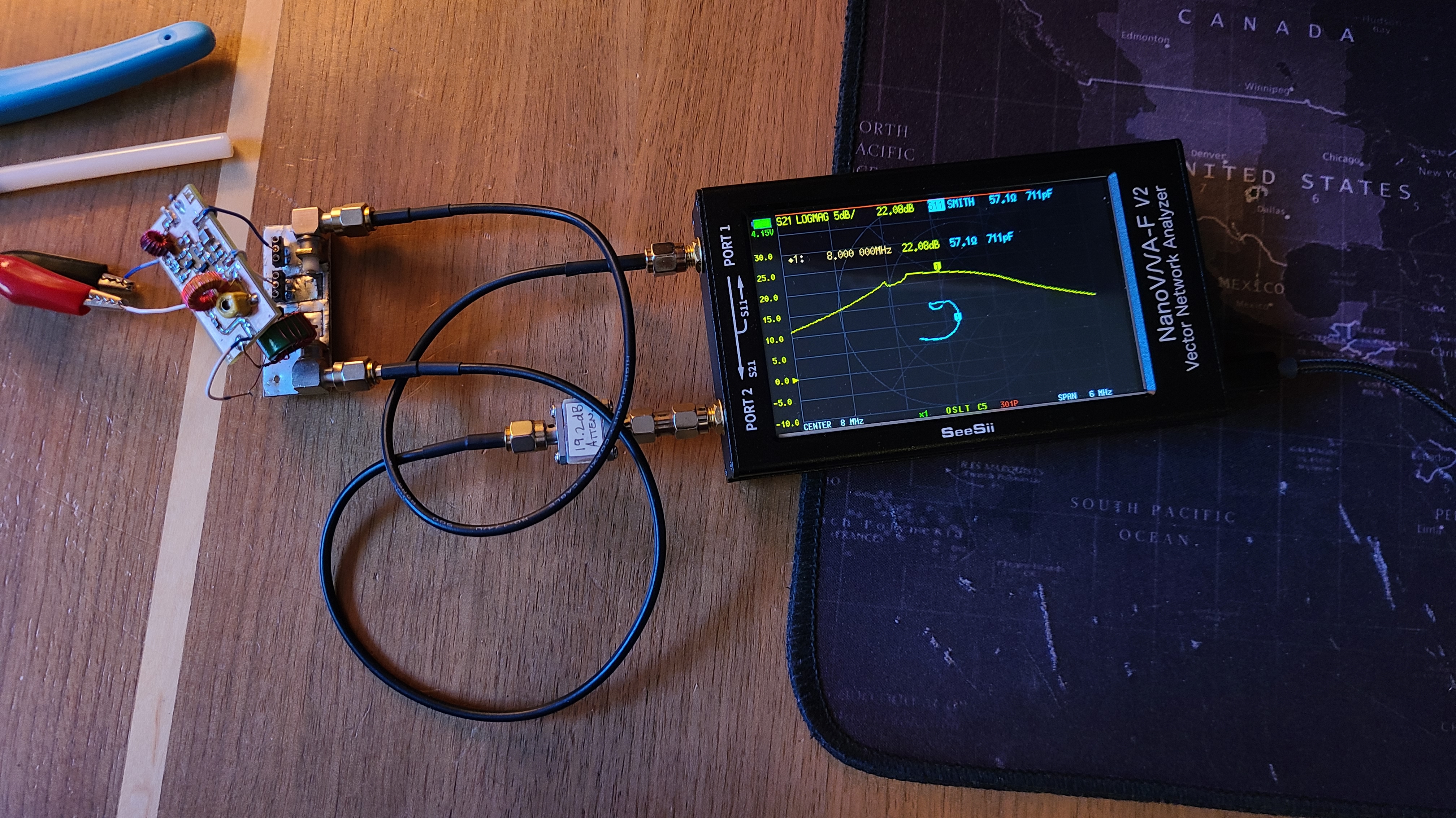
The results showed a gain of 22 dB at an input impedance of close to 50 Ω. The Q of the tuned tank seemed lower than I anticipated which could mean the tank circuit is getting loaded down more than expected.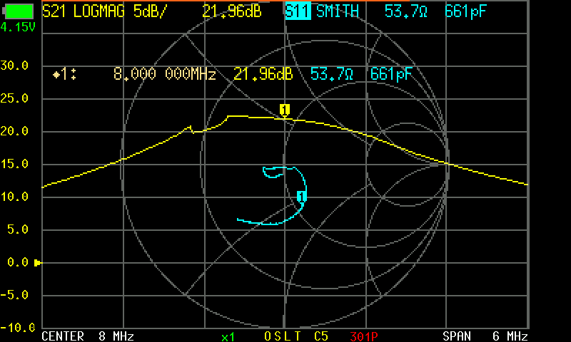
Remarks
This amplifier works well as the first IF amplifier. The tank circuit aids in selectivity, especially after the first mixer which may have unwanted mixing products.