After getting curious about vacuum tubes, nixie tubes, and later on vacuum flourescent displays (VFDs), I decided to go and give driving a VFD a shot. It seemed simple enough as I didn't need to use high voltages.
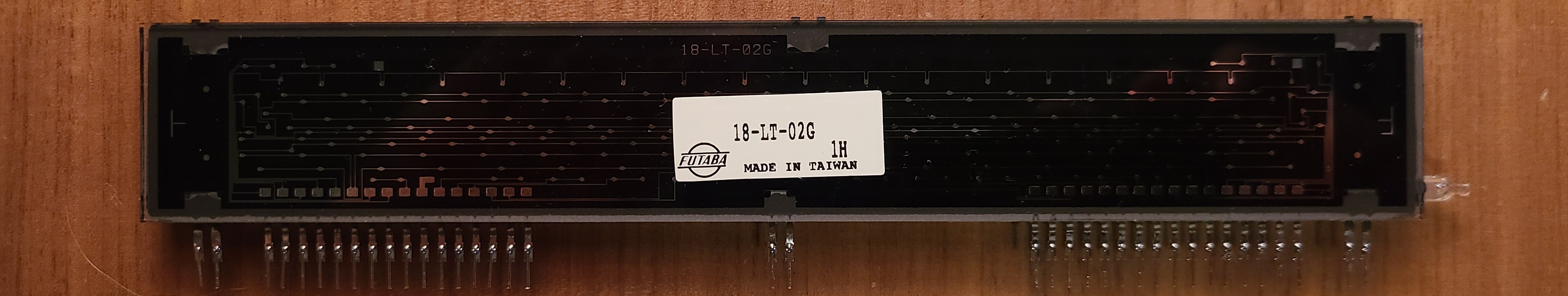
The VFD I chose to center this project around is a Futaba 18-LT-02G. It is an 18-digit 7-segment (plus some additional segments) display. I spent a decent amount of time looking for a datasheet on this display, but was unsuccessful.
I initially planned on using the MAX7219 7-segment display driver, as it can be cascaded. I quickly found out that each driver is able to drive 8 digits each and be cascaded to any number of digits, but each set of 8 digits has to have their own segment pins. My issue was, I had one set of segment pins for all 18 digits on the VFD.
The only way to drive this display was to design my own shift register driver. The complication with this approach was that I need a constant multiplexing loop in the microcontrollers code that would update the shift register for each digit. -- This however is a design for later. First, I need to get the display lit.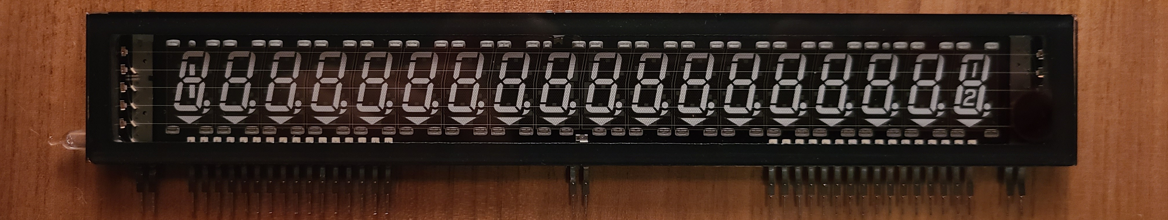
Filament Driver
First, to make the VFD function, the filament needs to be powered. The challenge with a display of this size however is that the filament needs to have an even distribution of charges. When the filament is powered with direct current, one side will have a positive charge, while the other is negative, meaning a gradient will form across the filament. This leads to uneven illumination of each digit. Typically, VFD filaments are driven with alternating current to combat this.
Experimentally, I found the Futaba 18-LT-02G requires about 3.3V RMS to illuminate the digits to a good brightness.
I tried two methods of driving the filament. First was the solid-state approach, where I designed an h-bridge that supplied the filament with the AC voltage required. My second approach was to use a transformer to produce the AC votlages for both the filament and for the anodes (grids/segments).
Solid-State Approach
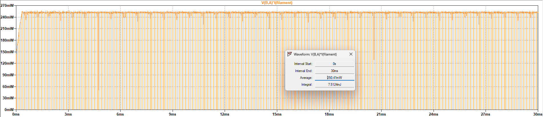
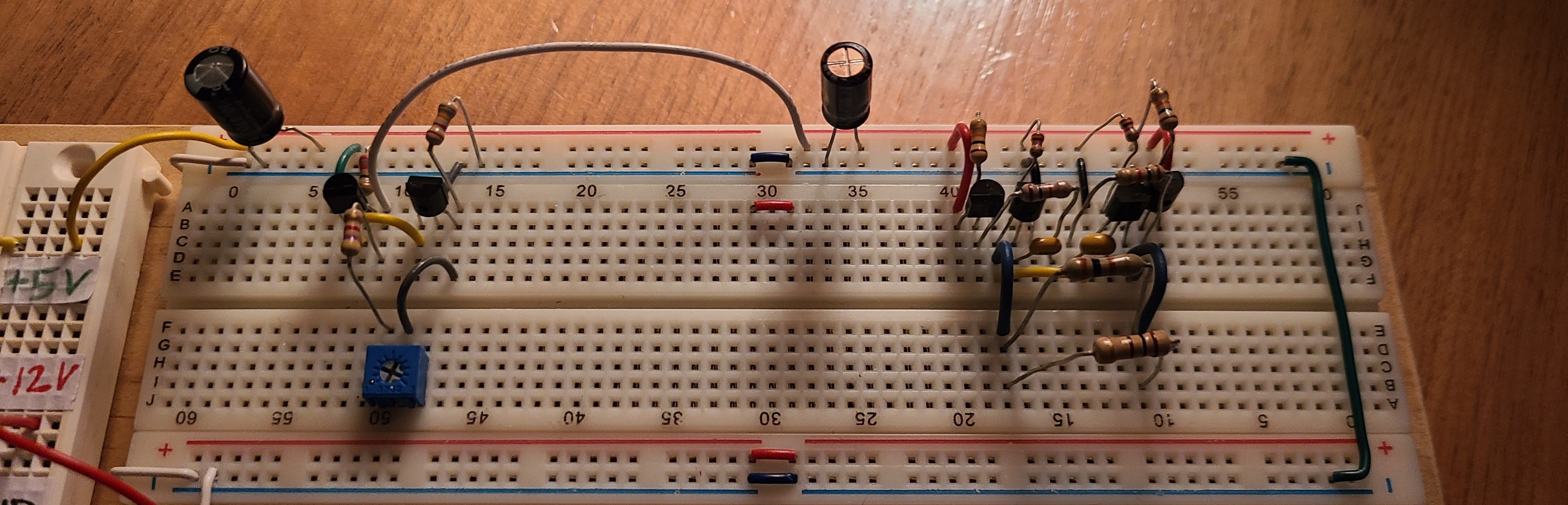
The strategy with the solid state approach was to have a 2-transistor astable multivibrator drive an h-bridge. The initial simulation showed promise, so I built it on a breadboard.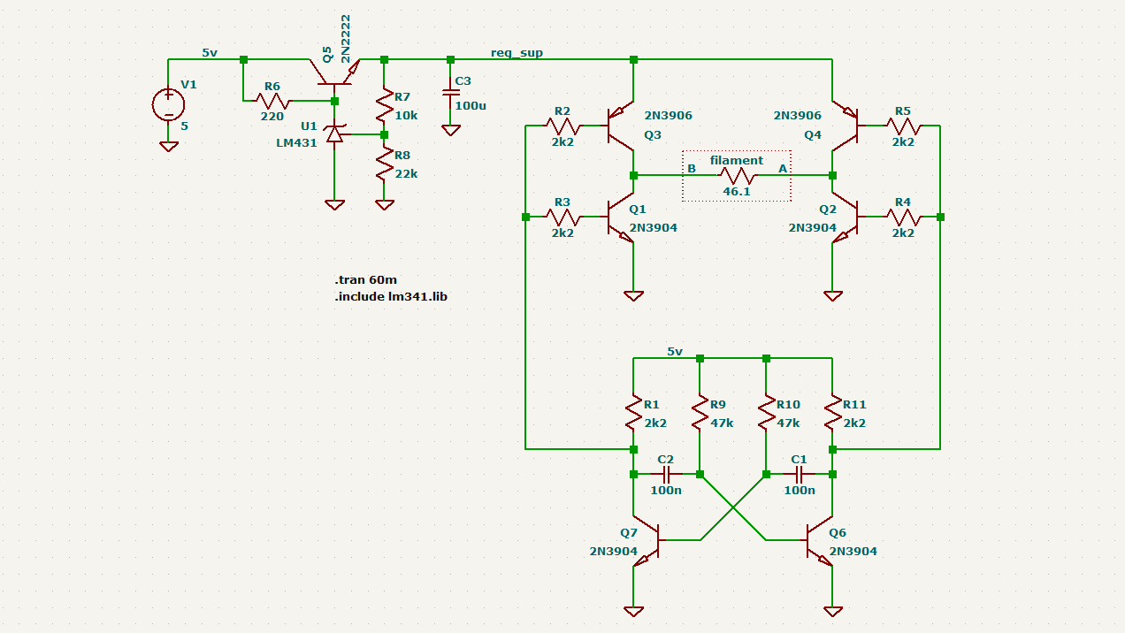
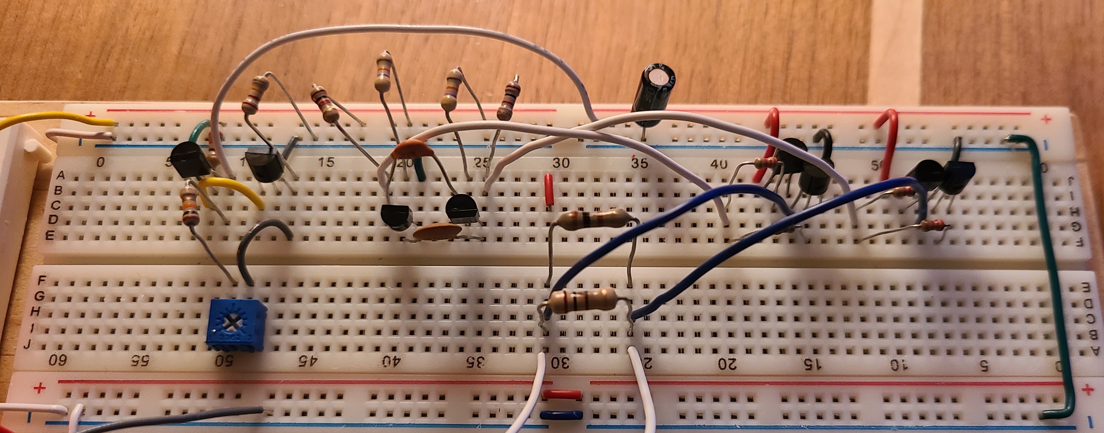
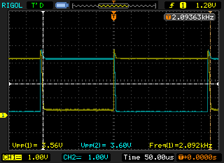
The results were a bit lackluster, so I looked at it longer and decided to turn the h-bridge into the astable multivibrator. This reduced component count and also made the h-bridge drive itself harder.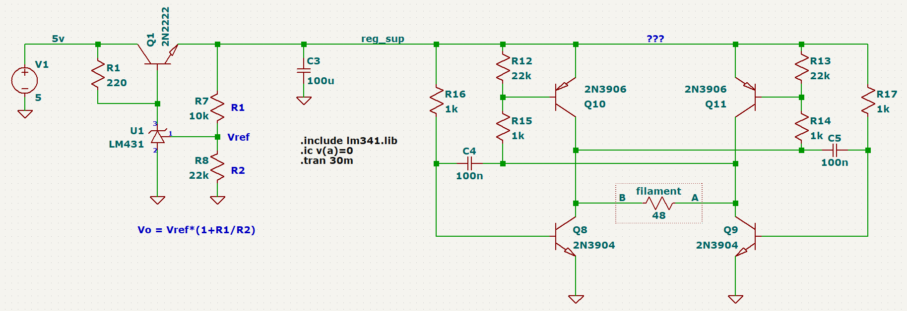

I use a TL431 adjustable voltage reference to set the filament voltage to fine tune the desired brightness.
Between the two versions, the second version uses fewer components and showed no downfalls compared to the first version, so I chose to stick with it.
Another neat observation was the change in supply power when the filament heats up, as the filaments resistance is lower when cold compared to when it is hot.
Transformer Approach
The classic method for achieving the voltages and power conversion needed for the VFD is by using a transformer. By using a transformer, I would be able to get my filament voltage as well as the anode (grid/segment) voltage needed to drive the display.
Using a random core I found, I measured the AL value (inductance / turns^2) and started designing the driving circuitry. The driver is a two transistor self-oscillating driver (Royer Oscillator).
The turns required to achieve each level is shown in the simulation schematic.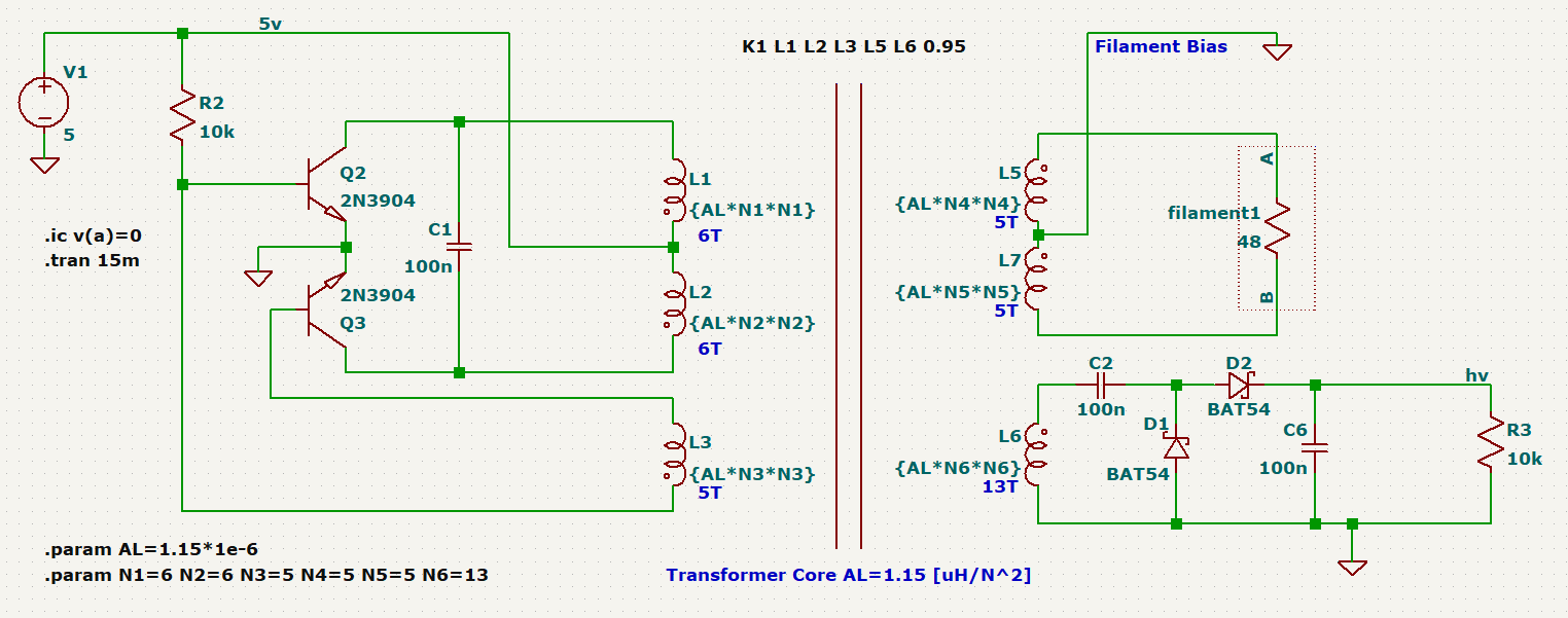
Note, on the second single winding at the output, there is a voltage doubler for the anode voltage. Ideally I want anywhere between +15V and +30V.
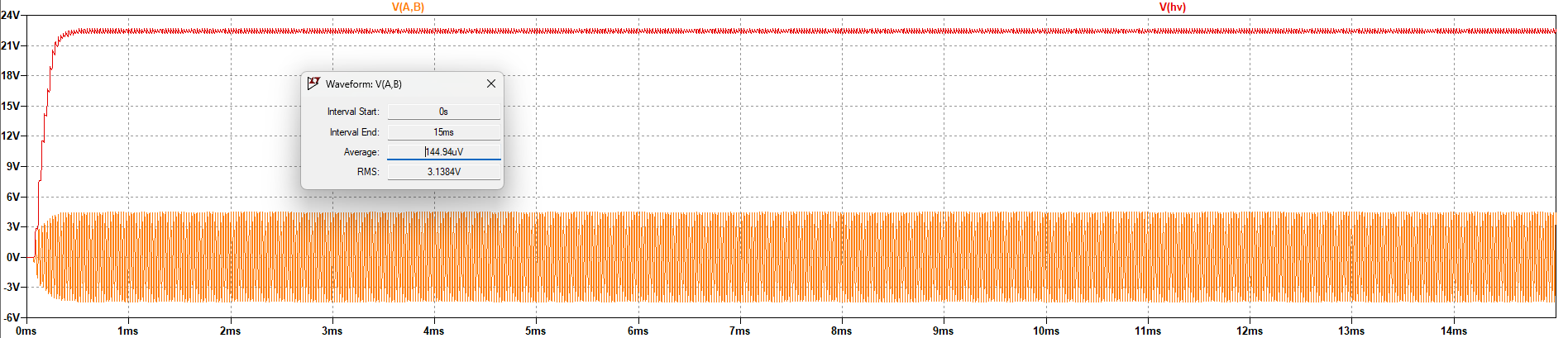
The transformer was wound, and tested to make sure all inductance values matched the schematic. Powering the circuit with 5 volts, and putting appropriate loads on each output, the results were measured on my oscilloscope.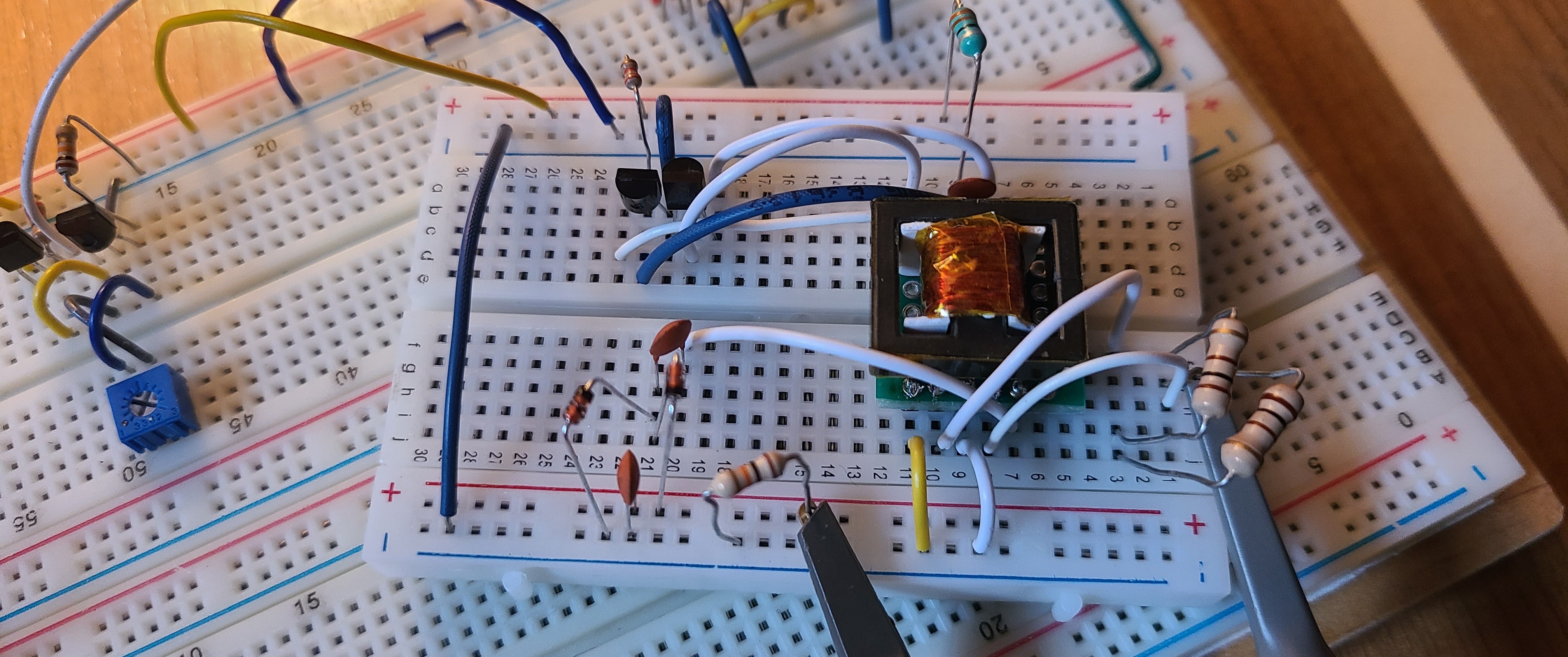
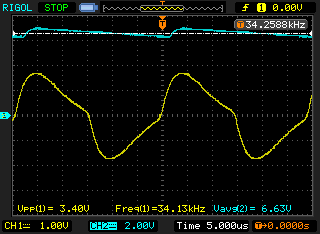
Immediately, I was running into problems with what I believe to be saturation of the transformer core. The sine wave was not clean, and the output of my anode drive voltage was far from the target value.
Remarks
I will look back into my notes and make measurements of the ferrite core I'm using. So far I haven't done any proper math of the core and "winged" the prototype. After figuring out the initial permeability, inductance per turn, and saturation current, I will revisit the transformer approach.
I may also look at some other methods of driving the transformer instead of using a royer oscillator. I like the idea of controlling the filament drive using PWM.