Milling PCB using CNC machine
In mid 2020 I purchased a mini desktop CNC milling machine for the sole purpose of milling out printed circuit boards (PCBs).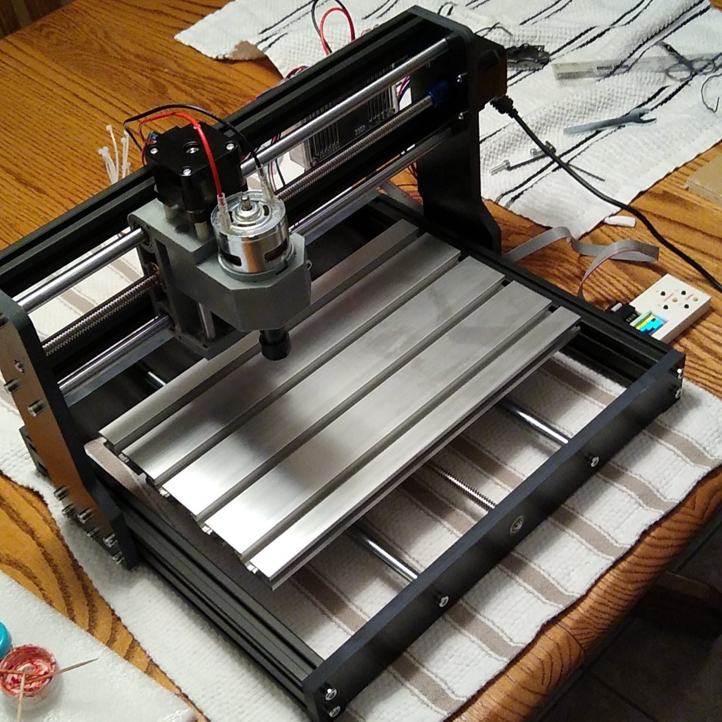
The CNC mill was controlled through a software called GRBL Candle, which read g-code instructions from a file and sends G-Code instructions to the CNC.
G-code serves as the standard alphanumeric programming language used to dictate the machine's toolpaths and operational commands. For example, the command G0 X10 Y20 Z5 instructs the mill to execute a rapid linear move to the coordinate position ($X=10$, $Y=20$, $Z=5$). For an exhaustive breakdown of individual commands and syntax parameters, refer to the Marlin G-code Documentation.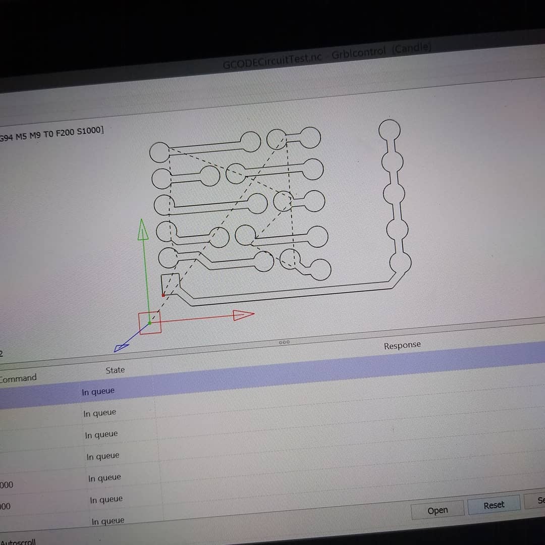
Process
For the purpose of milling PCBs, I needed a way to convert my gerber export files from EasyEDA (or KiCad) into g-code instructions for my CNC to execute. To do this, I found an application called FlatCAM, which allowed me to import gerber files, add and configure toolpaths, and configure the drilling paths for holes.
When milling a board, there are 2 major processes:
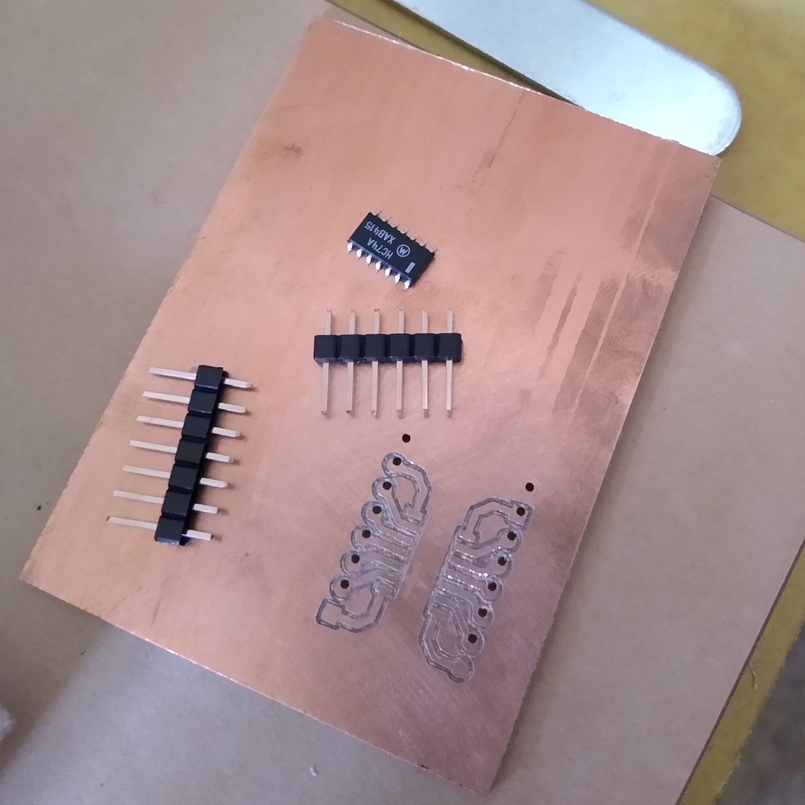
Isolating traces: where the outline of each trace is cut out.
Drilling Holes: where the various through holes are drilled and sized.
Before going straight into milling copper clad board, I wanted to tune in my FlatCAM configurations to get the best results possible. To run tests, I simply milled out some plywood I painted black.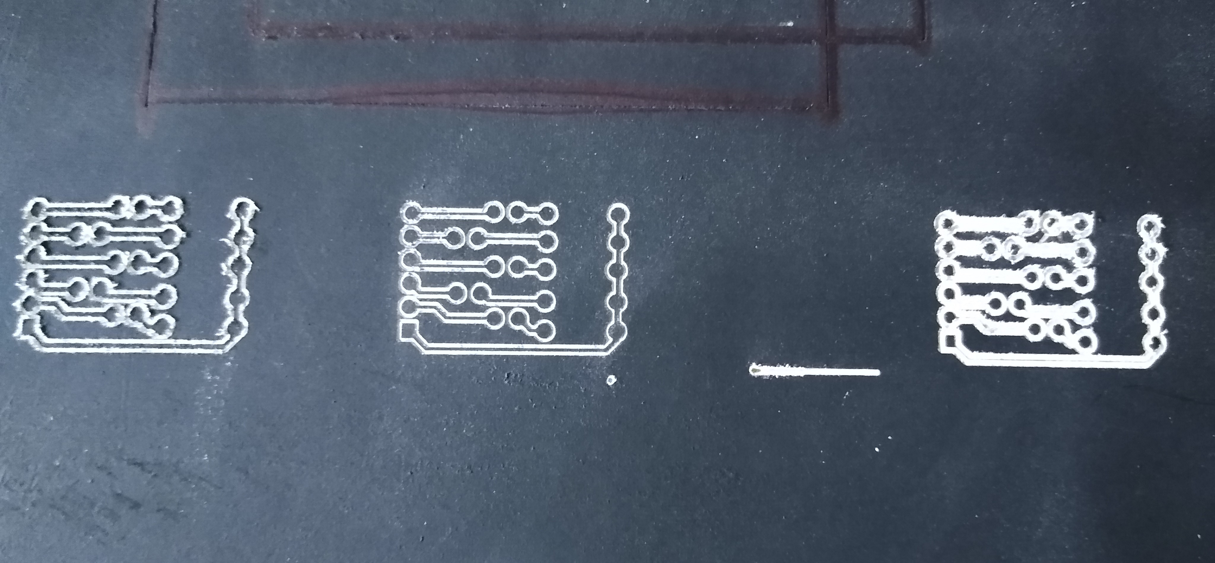
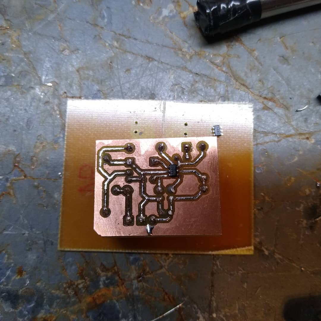
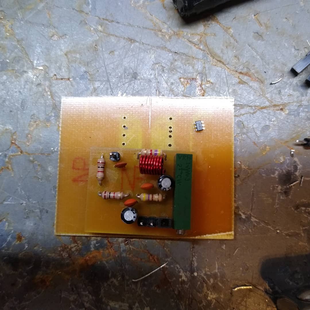
After the third revision of configurations, I had it dialed in quite well, so I made some PCBs using single sided copper clad board.
Results
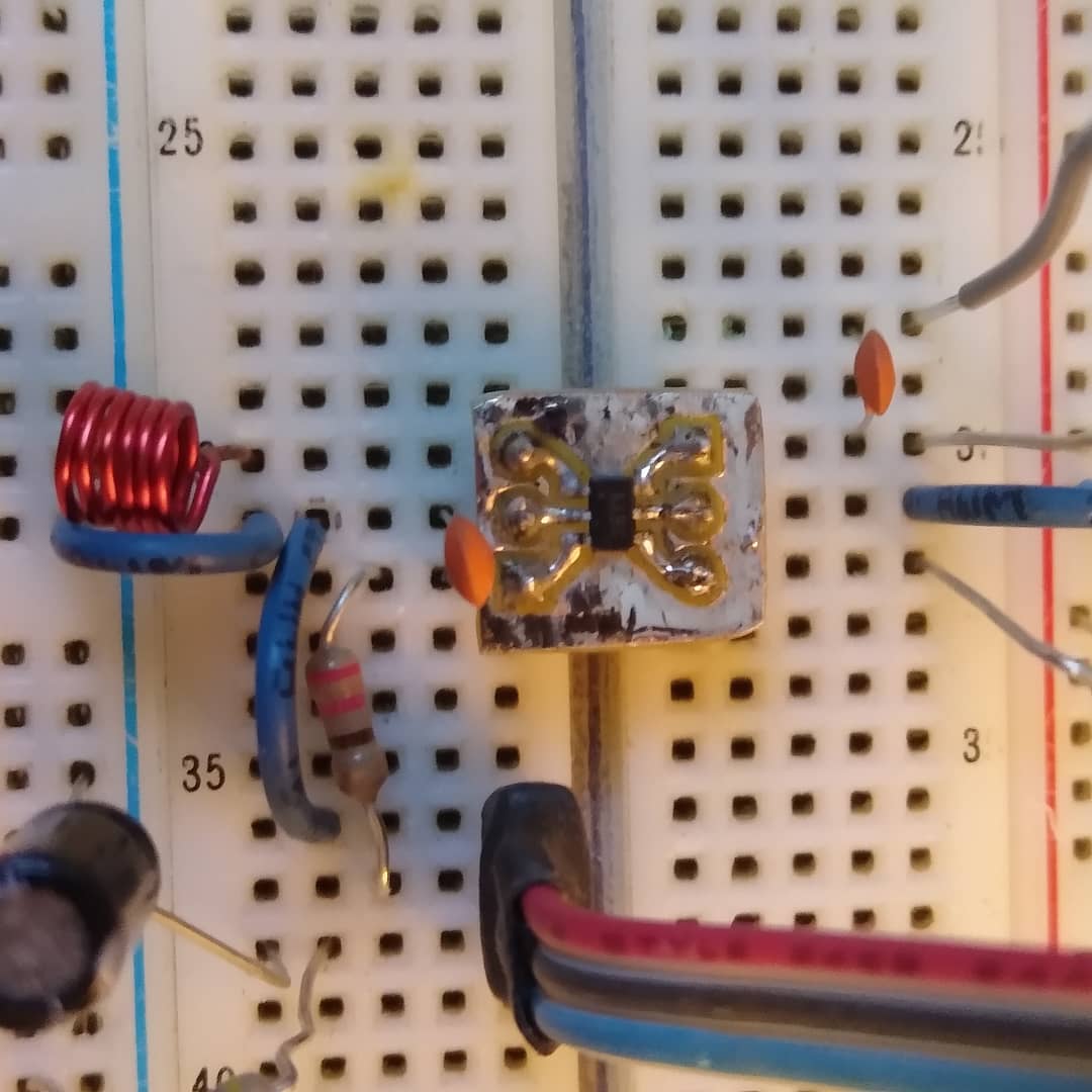
I had a number of failed attemts, but that never stopped me from trying again. I was able to create boards for various applications, such as SOIC to DIP test boards, and various boards for my projects.