During the spring of 2023, as part of my third-year course ENGR 320: Electromechanical Devices, my team was tasked with designing and building a functional motor or generator from scratch. The project came with a strict $100 CAD budget, a requirement for at least 20 seconds of sustained rotation, and a ban on using off-the-shelf motor parts. Because extra points were awarded for design complexity and self-starting capabilities, we chose to challenge ourselves by building a Three-Phase Brushless DC (BLDC) motor.
ENGR 320 Motor Design Project
Students were free to choose any type of motor, but additional points were granted proportional to the complexity of the design. For that reason, my group had chosen to design a brushless DC (BLDC) motor.
The design constraints/requirements were
- $100 CAD budget.
- Minimum 20 seconds of sustained rotation.
- Students aren't allowed to use existing motors or motor parts.
- Additional points awarded if motor is self starting.
The BLDC motor we created was a delta configuration with 8 rotor poles and 6 stator coils.
Building the Stator (6 Coils)
The coils were wound around M3 machine screws with 22 AWG magnet wire. All 6 coils were matched to be 54.5 ± 0.5 uH. We matched using inductance as it was easier than counting turns. (The coil turn count was approximated to be more than 200 turns of 22 AWG magnet wire). Coil dimensions OD: 13mm, ID: 3mm, length: 13mm.
Unfortunately, no picture of the coil winding process or finished coils were taken.
Rotor (8 Magnets)
The rotor was designed to hold 8 neodymium magnets and was 3d printed out of PLA. The design included space to fit a bearing to recude any friction. By winding the coils of the stator around screws, we were able to adjust the gap between the coils of the stator and magnets of the rotor.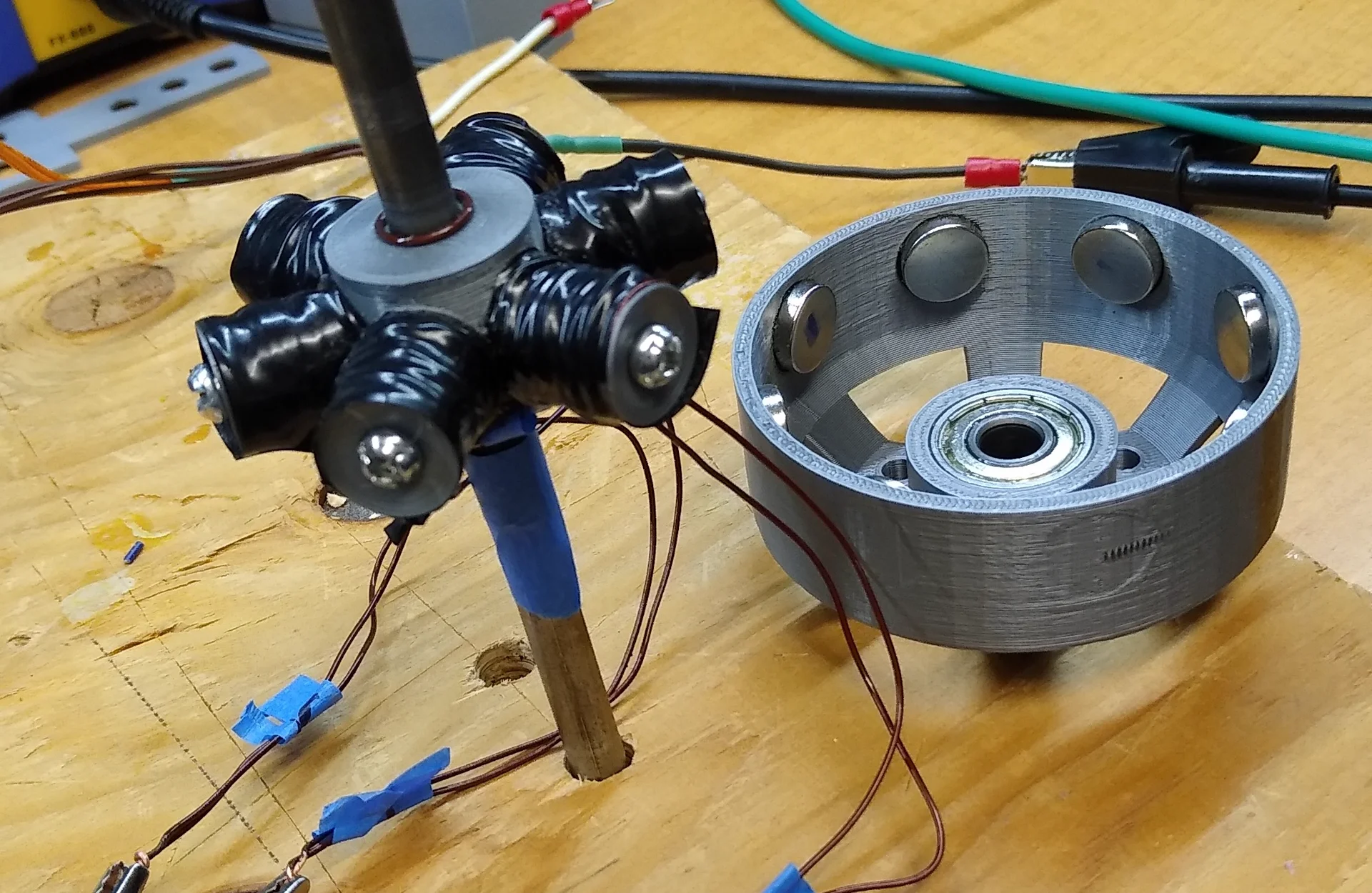
Variable Frequency Motor Driver (VFD, ESC)
To control the 3 phase BLDC motor, we needed to create (or find) a variable frequency 3-phase motor driver. We started out by designing our own.
The design consisted of 3 half H-bridges made from MOSFETS and an Arduino to control the gates. The control signal is not a sinusoid, but is usable. The sequence used for the motor was ABCABC.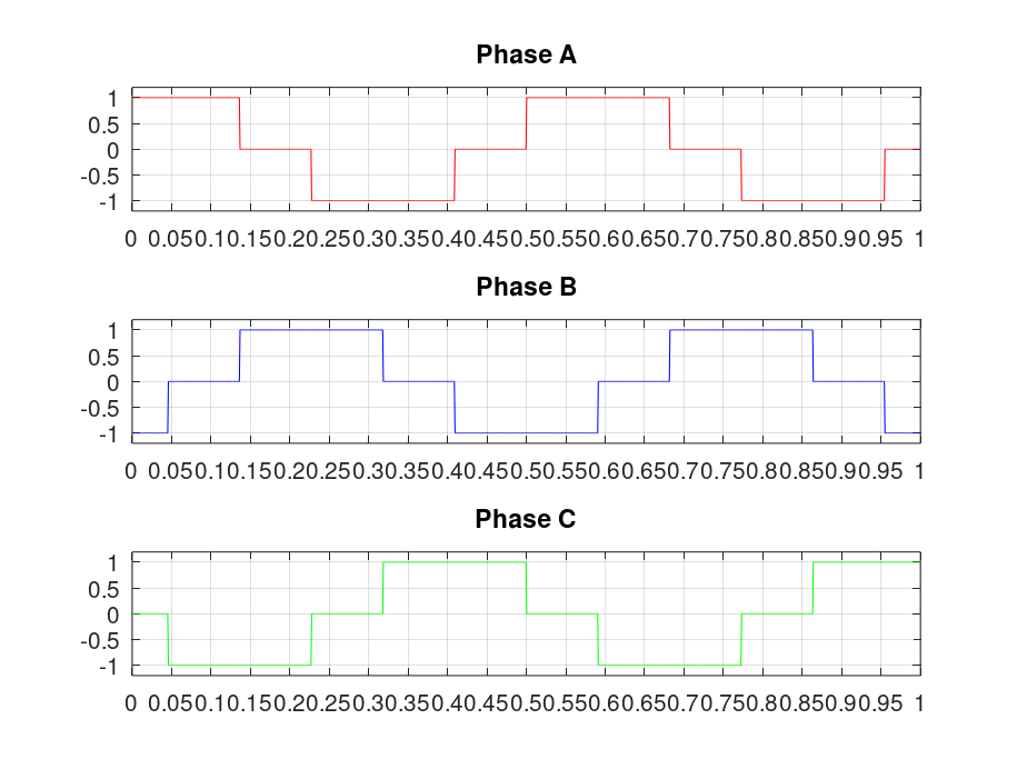
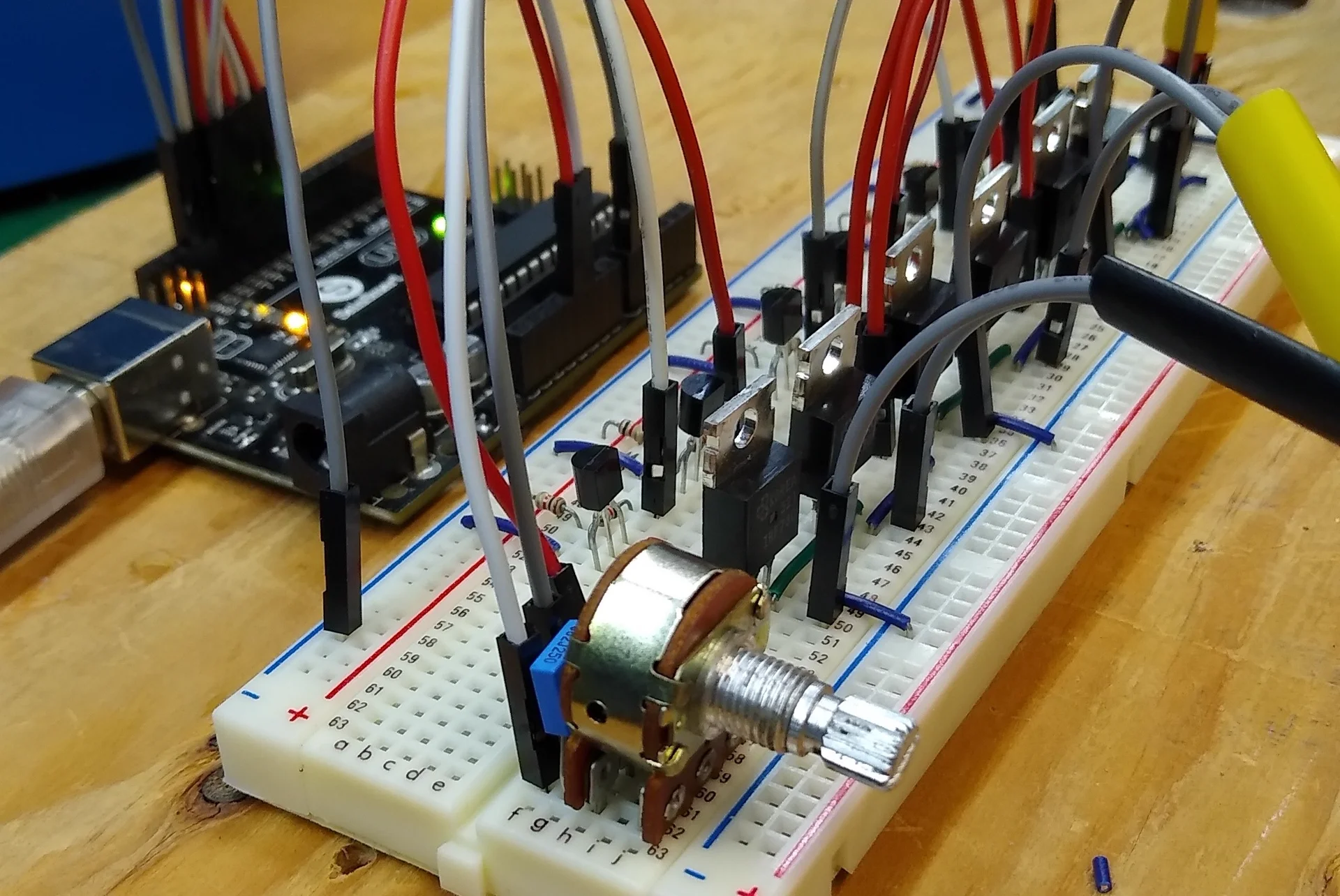
This design was very poorly implemented, and generated more heat than expected. This was quite bad as the motor was also not moving.
Being that the project was on a deadline, we decided it would be better to simply buy an ESC module for a BLDC.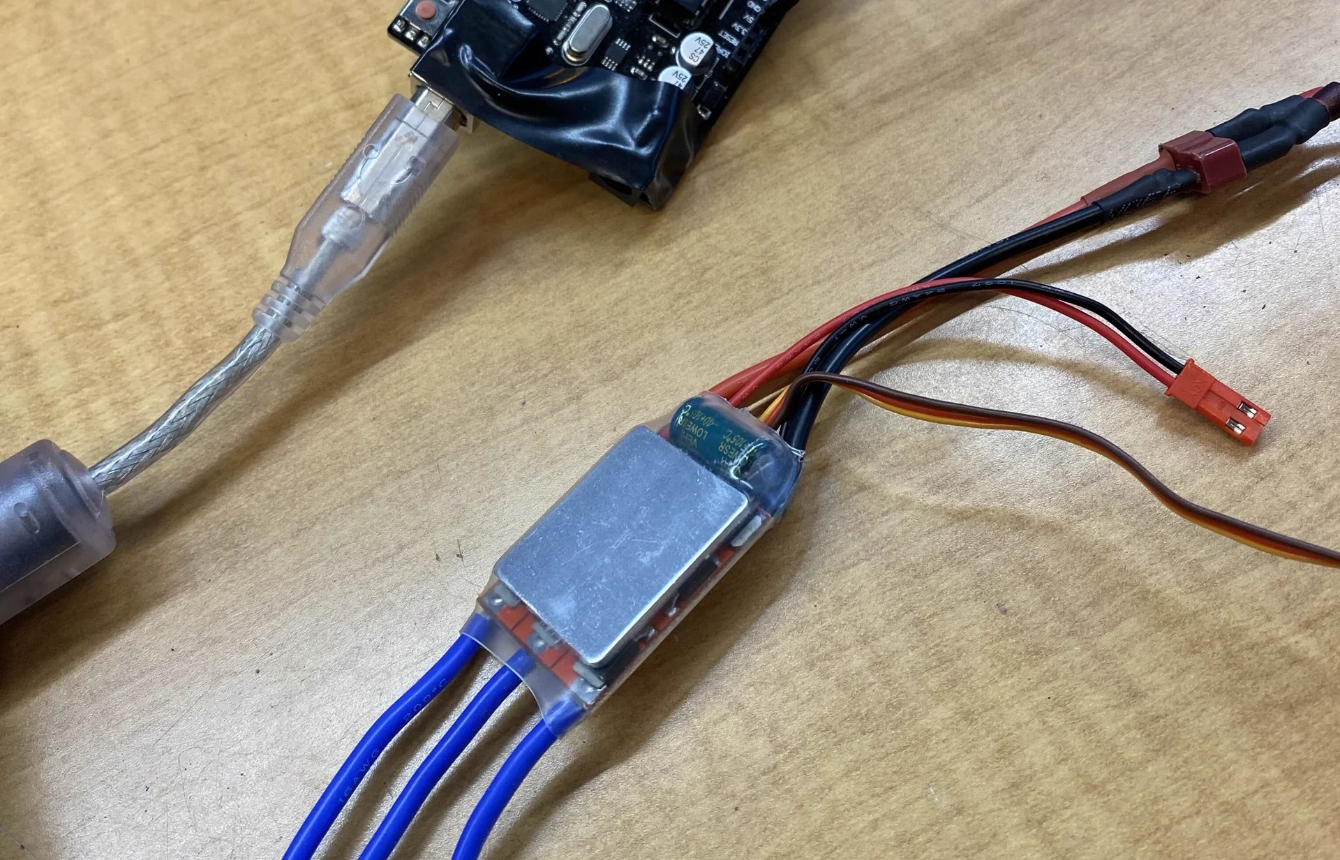
Using this ESC we were able to get the motor to run successfully.
Driver Soft Start
Due to minor physical imbalances inherent in a custom-built motor, requesting high acceleration from a static position caused inconsistent starting behavior and stalling. To overcome this inertia and ensure reliable self-starting, a software-based soft-start routine was implemented within the microcontroller code.
The algorithm functions by filtering the raw analog potentiometer input and introducing a dynamic ramp-up rate, preventing abrupt current spikes and synchronized lag:
val = analogRead(potpin);
  if (val < 10) val = 0;
  if (val >=10 && val <= 300) val = 300; // If knob is between 10 and 300, remap to start from 300 (0-300 is a deadzone for motor)


  escVal = map(val,0,1023,0,maxspd);


  if (spd != escVal){ // If speed knob has changed

    if (spd >= 150) del_set = 120;
    if (spd < 160 && spd >= 90) del_set = 90;
    if (spd < 90) del_set = 25;

    if ((millis()-del) >= del_set && maxspd == high && spd < escVal) {
      spd++;
      del = millis();
    }

    if ((millis()-del) >= 15 && maxspd == low && spd < escVal) {
      spd++; // In limited power, from 0/180 to 50/180, change relatively quick (Slow enough that it reacts fine)
      del = millis();
    }

    if (spd > escVal) spd = escVal; // When decreasing speed, decrease instantly
  }


  ESC.write(spd);   // Send the signal to the ESC
ESC Controller & Tachometer Code
To safely operate the motor and track benchmarking data, an Arduino Uno was integrated with a custom control panel and a telemetry sensor.
The hardware interface consisted of:
- A Potentiometer that acted as a manual throttle for precise speed adjustment.
- Dual-Mode Toggle Switch allowing the operator to select between two profiles: "Nerfed" Mode which restricted speed and current draw for safe troubleshooting, and Maximum Mode which unlocked full power to achieve peak RPM.
- An LCD Screen provided live visual feedback, displaying the current RPM and active soft-start state.
A Hall effect sensor was mounted adjacent to the rotor to track speed. As the 8 rotor magnets passed the sensor, the Arduino calculated the pulse frequency using hardware interrupts, translating the data into a real-time RPM reading for benchmarking. Arduino Code for the ESC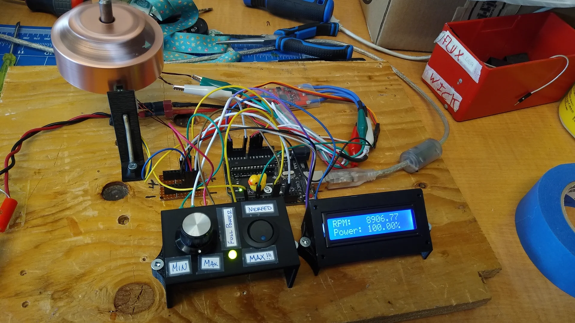
// =======================================================================================
// ESC Controller for the ENGR 320 Motor project
// By Michael Bell
// MARCH 2023
//
// As a group, we chose to add unecessary and extra features because we finished early.
// =======================================================================================

#include <LiquidCrystal_I2C.h>
#include <Servo.h>

// =======================
// Pin Definitions
// =======================

#define pwmPin 6 // ESC on pin 6
#define potpin A0 // Speed potentiometer on A0
#define sw 10 // Max/limited power switch
#define led 11 // Indication LED
#define hall 3 // Hall effect sensor pin (Must be pin 2 or 3)

// Constants
#define low 50 // about 28% power (50/180)
#define high 180 // max PWM speed

LiquidCrystal_I2C lcd(0x27, 16, 2);
Servo ESC;     // create servo object to control the ESC

int maxspd = low;
int val, escVal, spd, n;
float t_old=0, t_new, rpm, del, del_set;


void setup() {

  // =======================
  // Initialization
  // =======================

  Serial.begin(9600);
  pinMode(sw, INPUT_PULLUP);
  pinMode(led, OUTPUT);
  attachInterrupt(digitalPinToInterrupt(hall), tacho, FALLING); // Activate Tachometer interrupt when Hall sensor goes from 5v to 0v

  digitalWrite(led, 1);

  lcd.init(); //initialize the lcd
  lcd.backlight(); //open the backlight

  lcd.setCursor(0,0);

  ESC.attach(pwmPin,1000,2000); // (pin, min pulse width, max pulse width in microseconds)
  ESC.writeMicroseconds(900); // send “stop” signal to ESC.
  delay(2000); // delay to allow the ESC to recognize the stopped signal

  // =======================

  while (analogRead(potpin) >= 8) { //Check for knob to be zeroed, if not, wait until it is
    digitalWrite(led, 1);
    delay(500);
    digitalWrite(led, 0);
    delay(500);
  }

  digitalWrite(led, 0);

  lcd.clear();

  lcd.setCursor(0, 0);
  lcd.print("RPM: ");
  lcd.setCursor(0, 1);
  lcd.print("Power: ");

}

void loop() {

  // ==========================
  // Full/Limited Power Switch
  // ==========================

  int spdpin = digitalRead(sw); // read full power switch

  if (spdpin == 0 && val <= 10 && maxspd == low) { // if switch is on, knob is zeroed, and the max speed is low, then allow full power
    maxspd = high;
    digitalWrite(led, 1);
  }

  if (spdpin == 1 && val <= 10 && maxspd == high){ // if switch is on, knob is zeroed, and the max speed is max, then go to quarter power
    maxspd = low;
    digitalWrite(led, 0);
  }


  // ================================================
  // Speed Control, Full/Limited Power soft control
  // ================================================

  val = analogRead(potpin);
  if (val < 10) val = 0;
  if (val >=10 && val <= 300) val = 300; // If knob is between 10 and 300, remap to start from 300 (0-300 is a deadzone for motor)


  escVal = map(val,0,1023,0,maxspd);


  if (spd != escVal){ // If speed knob has changed

    if (spd >= 150) del_set = 120;
    if (spd < 160 && spd >= 90) del_set = 90;
    if (spd < 90) del_set = 25;

    if ((millis()-del) >= del_set && maxspd == high && spd < escVal) {
      spd++;
      del = millis();
    }

    if ((millis()-del) >= 15 && maxspd == low && spd < escVal) {
      spd++; // In limited power, from 0/180 to 50/180, change relatively quick (Slow enough that it reacts fine)
      del = millis();
    }

    if (spd > escVal) spd = escVal; // When decreasing speed, decrease instantly
  }

  ESC.write(spd);   // Send the signal to the ESC

  // =======================
  // LCD Output
  // =======================

  if (n == 15){
    n = 0;
    lcd.setCursor(7, 0);
    lcd.print(String(rpm)+"          ");
  } else n++;

  lcd.setCursor(7, 1);
  lcd.print(String((float)spd * 100 / high) +"%          ");

  //Serial.println(String(spd) + "," + String(escVal) + "," + String(val) + "," + String(maxspd) + "," + String(rpm));
  //Serial.println("Speed: " + String((float)spd * 100 / high) + "%,  RPM: " + String(rpm));

}

void tacho() {
  // =======================
  // Hall Sensor Tachometer
  // =======================
  float rpm_0 = rpm;
  float rpm_1 = rpm_0;
  float rpm_2 = rpm_1;

  t_new = micros() ;
  float period = (t_new - t_old)*4/1000000; // 8 magnets on rotor, 4 of them will make hall sensor go from high --> low, so we multiply time by 4.
  t_old = t_new;

  rpm = ((1/period)*60 + rpm_0 + rpm_1 + rpm_2)/4;

}
Result
The motor ran on 12V DC with a current draw of around 2.8A at no load full RPM. Overall, the motor ran quite well.