Back in 2022, I took on the challenge of upgrading the Brake System Plausibility Device (BSPD) for the UBCO Motorsports club, taking it from an existing concept to a fully realized PCB. Because it was my first large-scale board design, this project holds a special place in my engineering journey and added to my passion for hardware development.
The purpose of the BSPD is to kill the engine of formula SAE (FSAE) car that the Motorsports club was designing. The BSPD is a safety system that monitors for dangerous conditions where hard braking occurs simultaneously with high power output to the motors, indicating a fault.
BSPD FSAE Rules and Requirements
In 2023, students were told to follow the 2019 FSAE rules in the design for the BSPD, so the following requirements were to be met: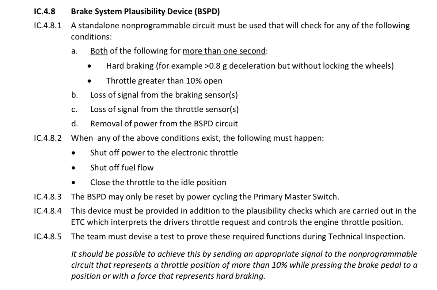
A summary of the requirements that need to be met would be:
- Given both hard braking (0.8*g deceleration) and throttle greater than 10% occurs for more than one second, kill the motor, fuel flow to the motor, and close the throttle to idle position.
- The BSPD can not contain any programmable components such as microcontrollers.
- The circuit can only be reset through cycling the power.
BSPD Design
Sensors will output an analog voltage (or current) between 0.5V and 4.5V. If the voltage falls under 0.5V or over 4.5V, the sensor is considered have a fault. Given the sensors operating range is known, the circuit was designed as per the requirements.
Comparator
The first step to the design was measuring the analog sensor signals and discretizing them using a comparator. The comparator used was the TI LM393.
There are two of the comparator circuits, one for implausability 1: hard braking, and implausability 2: throttle > 10%.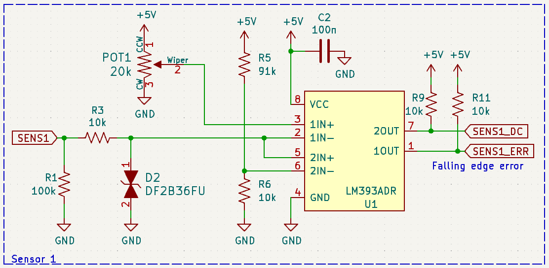
The sensor is connected to both the comparators inputs in such a way that, utilizing both the comparators in the dual-package IC, both a disconnect (sensor voltage below 0.5V) and implausability can be detected. The disconnect threshold is set by a voltage divider that outputs a reference voltage of 0.495V. The implausability threshold is set with a 20k trimmer potentiometer.
A transient voltag suppression (TVS) diode was added to the sensor input for electro-static discharge (ESD) protection to the LM393.
Lastly, the LM393's output is an open-collector, so the outputs were pulled up to 5V via 10k ohm resistors for the digital logic section.
Logic and Timing
The logic circuitry starts by taking the implausabilities of both sensors and using a NOR gate to detect when both the implausability errors occur. Using an OR style gate seems counter intuitive for an AND operation, however, because of the open-collector comparator needing pullup resistors, the comparator outputs a LOW when there is an error, so the NOR only goes HIGH when both implausabilities occur. Likewise, for the disconnect error, we want to trigger the device when either of the sensors have a disconnect error, so a NAND was used.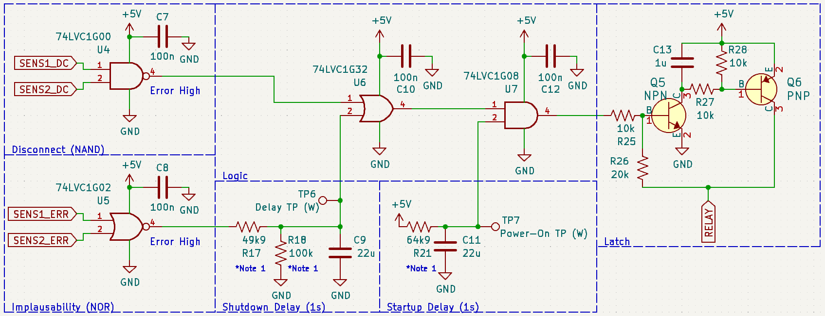
Following the implausability error gate, an RC network handles the timing of the shutdown. The logic gate ICs have a LOW-HIGH threshold around 2.5V, so the RC values were calculated to charge to 2.5V in 1 second.
Finally, if there is a disconnect error, or an implausability, and the BSPD has been powered up for longer than 1 second, a latch is triggered.
The latch circuit operates similarily to a silicon controlled rectifier (SCR) as it has an PNPN junction structure. In a future revision of this circuit, the latch circuit was swapped out for a discrete SCR.
Shutdown Timer Calculation
The shutdown timer was designed in such a way that the capacitor could discharge through a shunt resistor. This was done to prevent small occurrances of implausability errors from compunding.
To calculate the timing of this RC network, the following calculations were made. A Desmos Calculator was also made for this formula.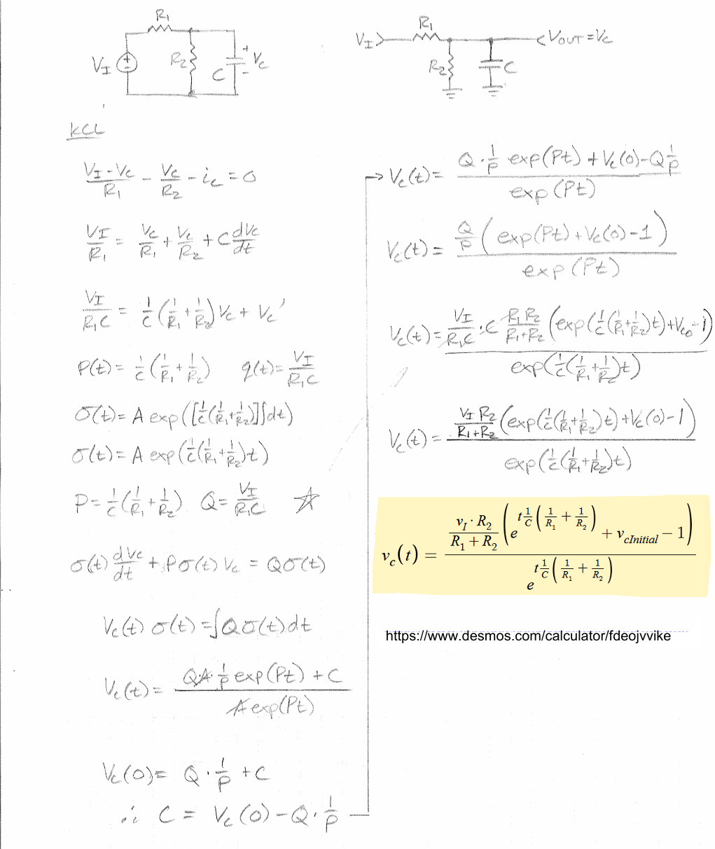
Relay, LED indication, and Connector
The relay and status LEDs were driven with MOSFETs. The relay itself was powered from the 5V source, and triggers the connection to the ECU to kill the engine.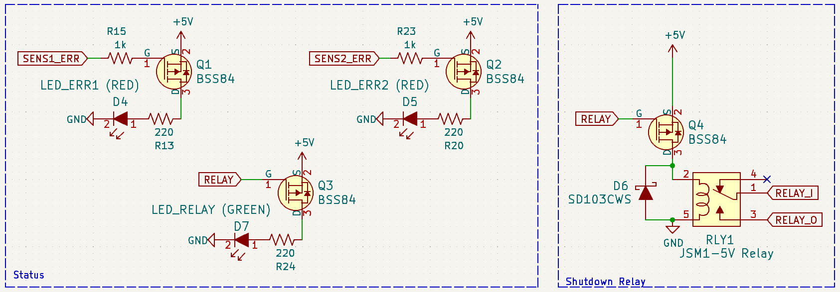
Coming from the connector is the cars voltage supply, which is dropped to 5V using a linear regulator. All test points are connected to key lines to measure the RC timers and various digital states.
The 1N4007 rectifier diode connected to the 12V supply was implemented to prevent damage in the case of reverse polarization. Additionally, the TVS diode was added to prevent any ESD damage.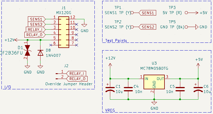
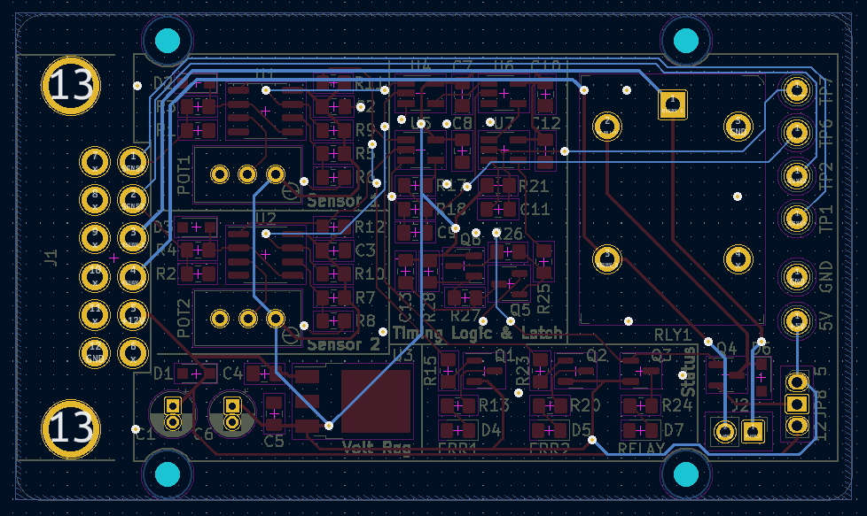
PCB Design and Assembly
With the schematic set, the PCB was designed in KiCad. The PCB was layed out similar to the schematics layout, and all groups are labeled clearly with silkscreen. This was done so the judges could understand how the circuit functioned at a glance.
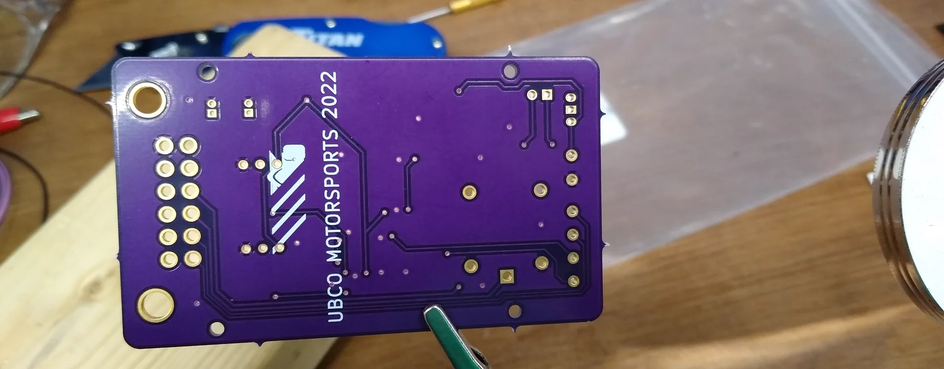
The PCB was designed to be a two sided board, with FR4 substrate. The simplicity of the circuit allowed for minimal use of the second layer.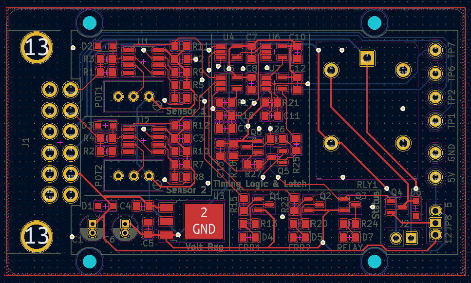
After ordering and recieving the PCB from OSH Park and getting the necessary components from Digi-Key, we started populating the PCB with its components.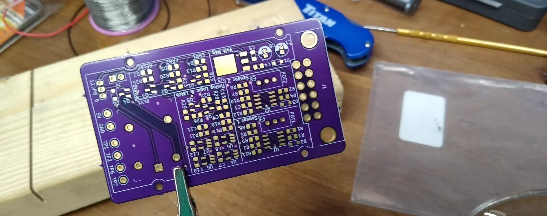
The assembled board turned out well. Now all that is left is tuning the comparators thresholds to trigger at the correct sensor levels.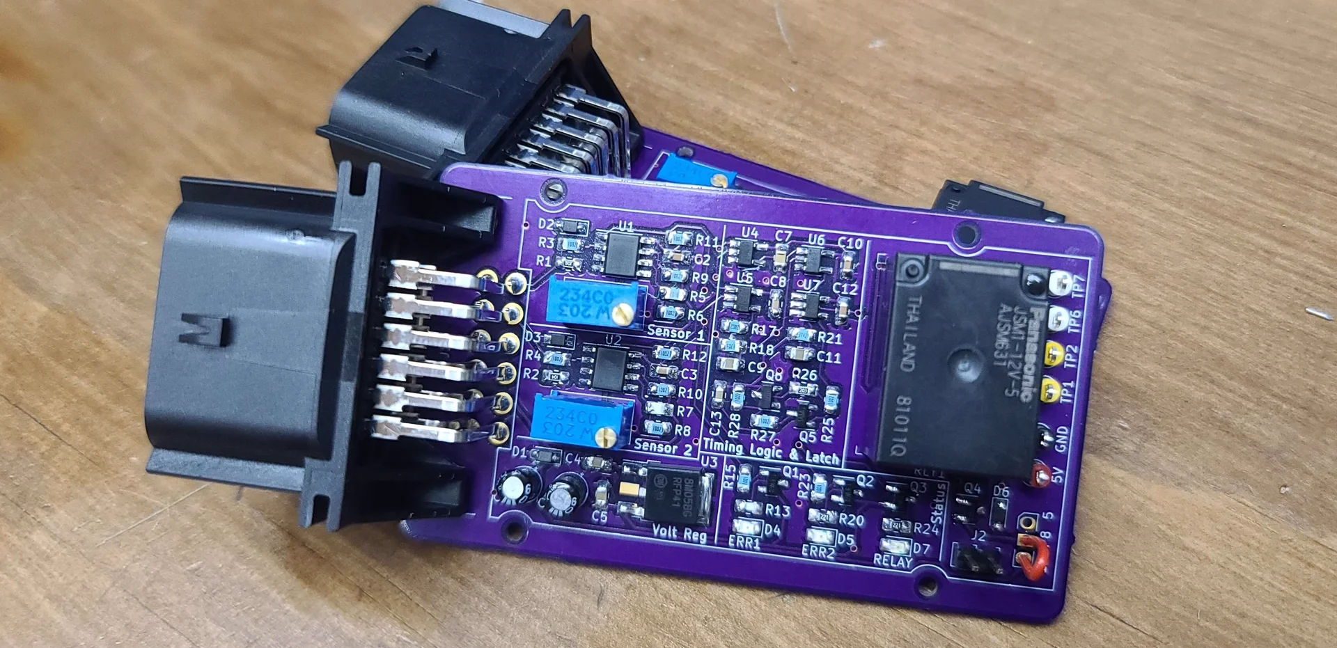
Testing
After assembly, the board was tested to ensure timings fell within the 1 second requirement. The test setup consisted of an arduino for data acqisition and voltage supply to simulate the sensors output.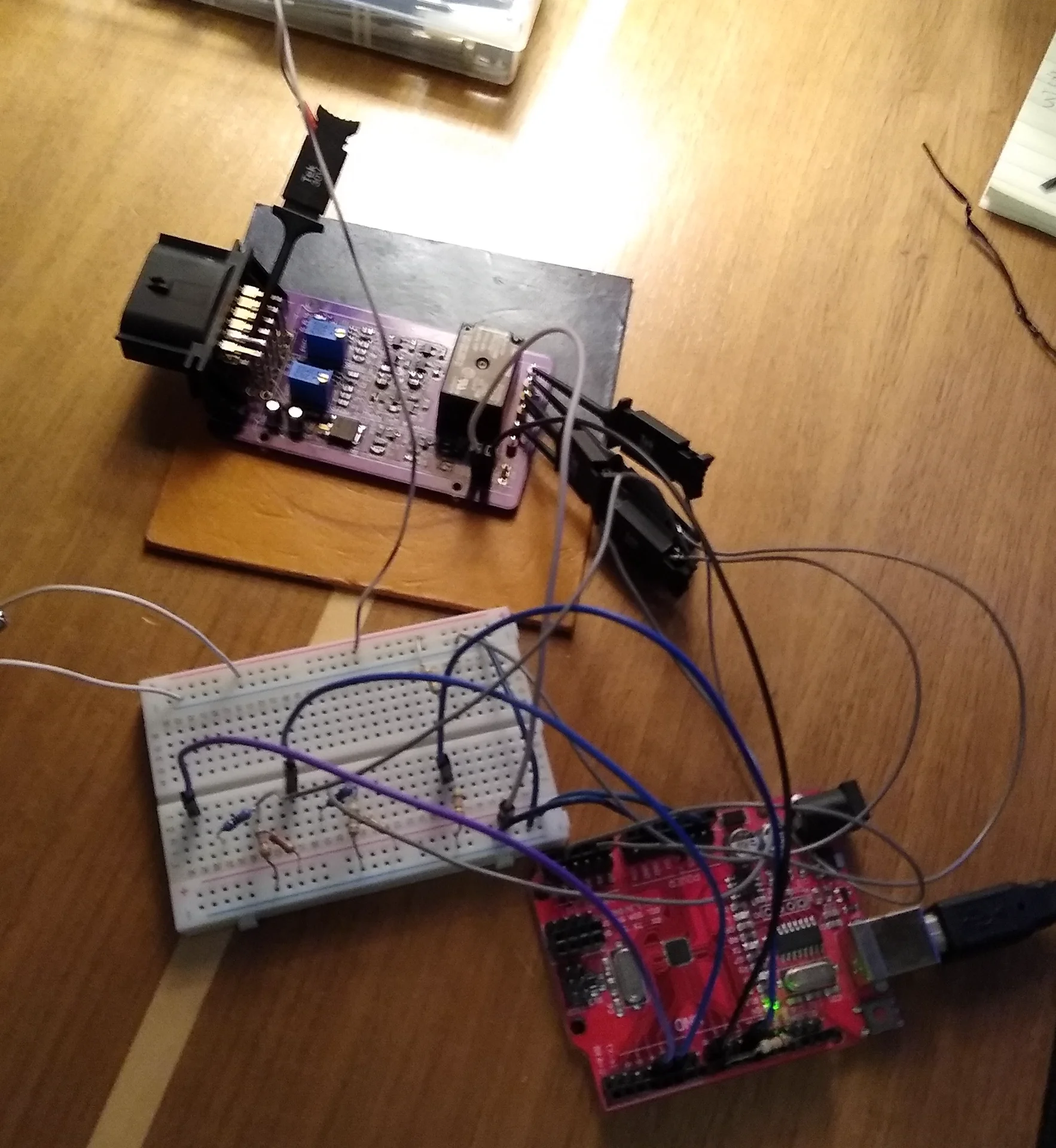
The results from testing (at a room temperature of 23 degrees celcius) showed the startup timer to be 0.977 seconds and the shutdown timer to be 0.967 seconds. Both timers trigger under the maximum 1 second requirement.
When the error state goes low, the shutdown timer begins, and the relay is powered after the shutdown timer reaches its logic threshold voltage. This is shown below in the test results.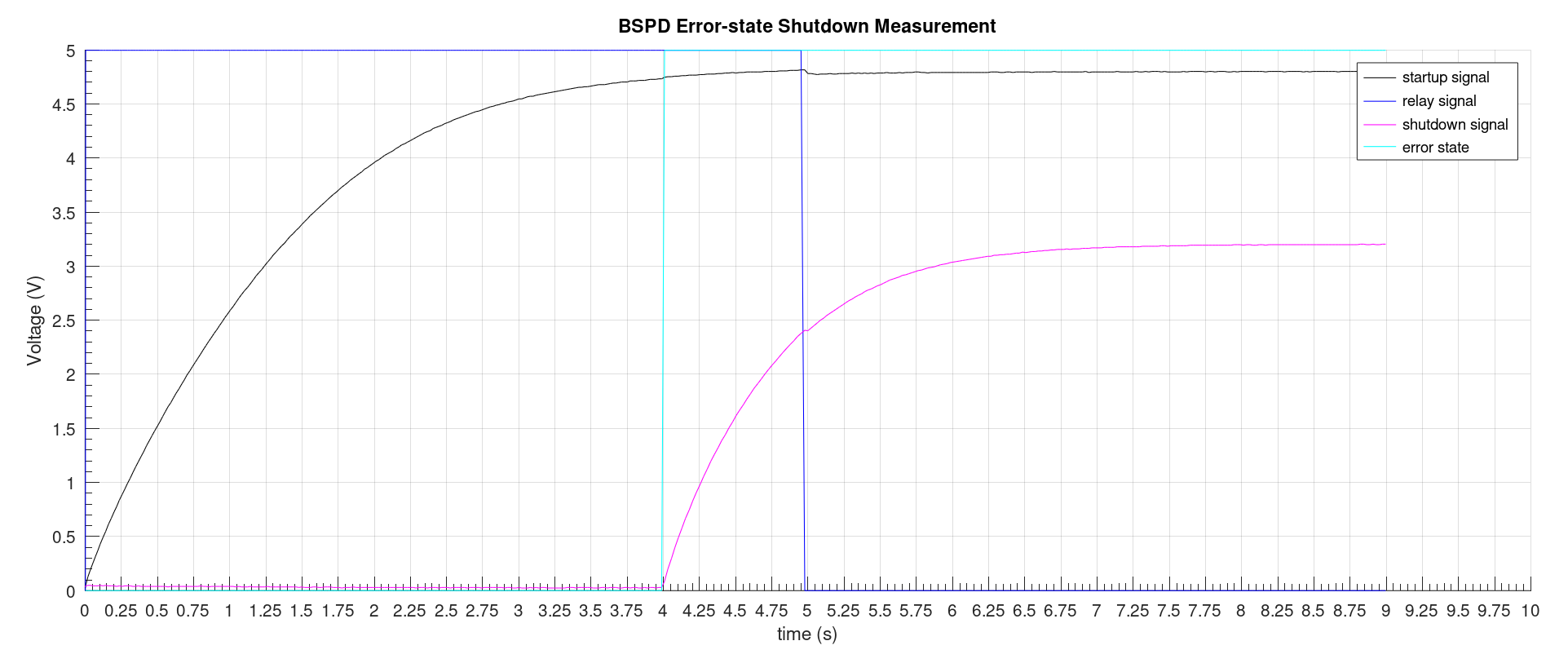
Results
The BSPD project was a success across every phase of the design, manufacturing, and real-world implementation. The finalized PCB was integrated into the vehicle and operated correctly during technical inspection, and was officially passed by the FSAE competition judges.
As one of my very first hardware designs, this project was a foundational learning experience. Navigating the strict regulatory constraints of FSAE rules, calculating analog timing circuits, and managing a complete hardware production cycle gave me technical confidence. This milestone ultimately solidified my passion for hardware engineering and set a strong benchmark for all my future PCB design work.