My younger brother had bought some FANATEC race simulation pedals from Facebook Marketplace, but when he went to set them up, they didn't work. After fighting with them for a while, he brought it to me to fix. The issue was in the main board, which had been damaged due to the wrong plugs being inserted in incorrect sockets, which the instructions stated could damage the board.
Because of the damaged main board, I decided that I would build my own main board. To do this I utilized the integrated USB human interface device (HID) support the Atmel ATmega32u4 microprocessor has. The microprocessor development board used was a spin-off of the Arduino pro micro.
Retrofitting Pedal Hardware
The pedals consisted of two hall-effect sensor controlled inputs and a load cell input. The center pedal (brake) used a load cell, and the left and right pedal (clutch and acceleration respectively) used analog hall-effect sensors to determine position.
After gutting the internal electronics of each pedal, I began putting together the circuit on a solderless breadboard.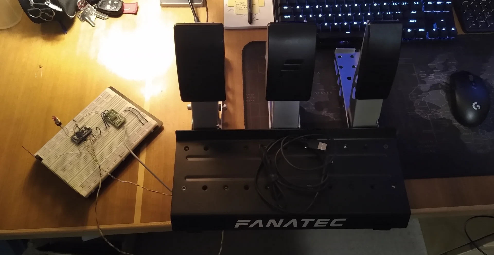
Breadboard
Since the pedals needed two hall effect sensors and a load cell amplifier, I made the necessary purchases on amazon to get the parts right away. Overall, it only cost me CA$30. I began prototyping by connecting the hall effect sensors to the microprocessors analog input pins. These analog inputs operate on a 10-bit analog-to-digital converter (ADC), allowing for a resolution of around 4.88 mV (at a supply voltage of 5V), which would be plenty for the hall effect sensors.
The load cell required an amplifier to get any useful amount of data from it. The amplifier I used was an Avia HX711. This amplifier is fairly common and easily sourced, and provided 24-bits of resolution, which was way more than I needed -- I later configured the HX711 in the code to read at a higher speed at cost of the precision.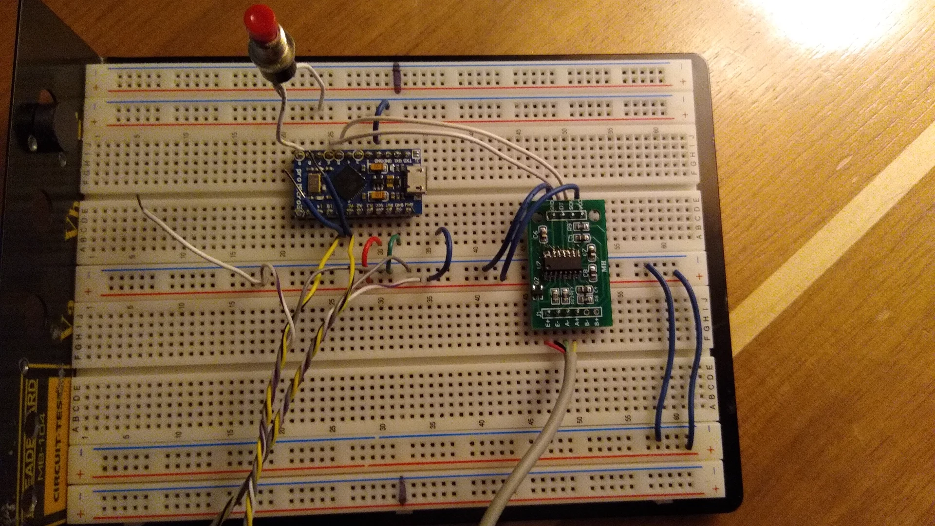
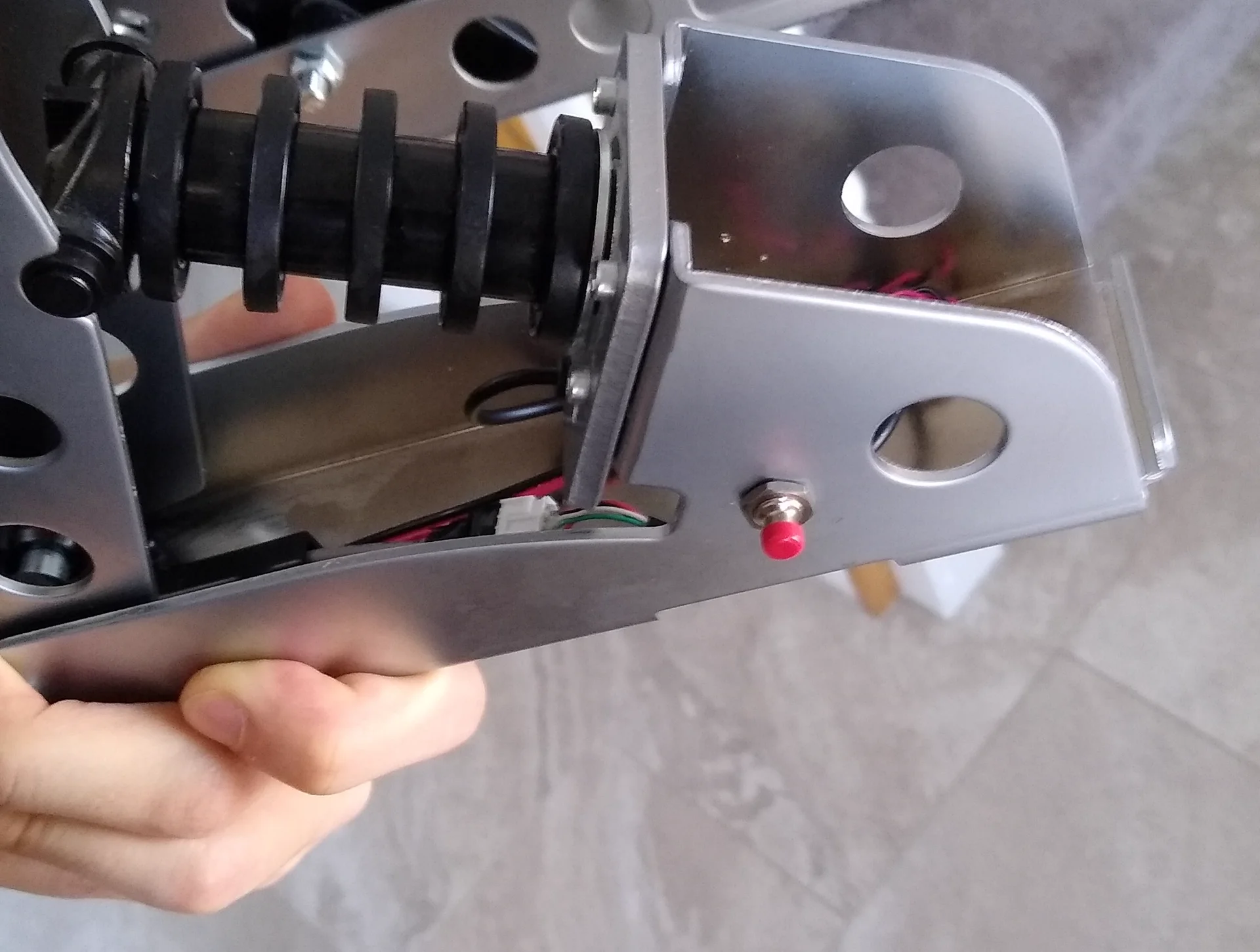
I also included a button for user input. This button allows the user to calibrate the pedals or to reset the calibration to default.
Main board design
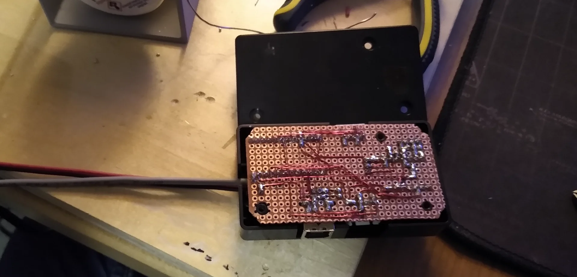
The pedals originally had its main board in a box at the bottom of the middle pedal. The goal for me was to fit all my electronics inside that same box. To start I measured out where I needed to make holes, then planned where I would place the components.
Because I was trying to expedite the project and finish it in a day or two, I opted to use perforated proto-board. This meant that the microprocessor development board and HX711 could be placed down as-is (almost)...
To make the HX711 fit on the main board, I had to de-solder the IC from the development board I got from amazon, and transplanted it onto an SOIC to DIP breakout board. This would be easy if I had a hot-plate, but I didn't at the time, so I had to use the next best method: clothing iron.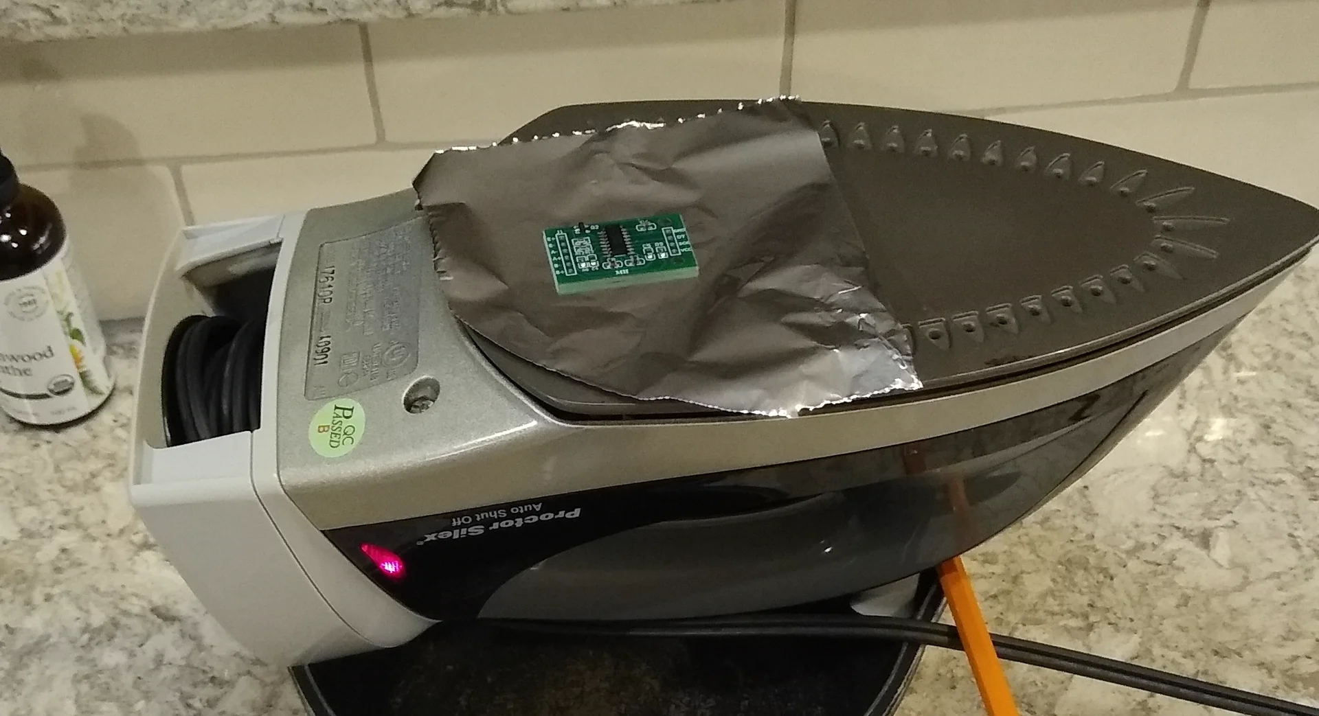
By balancing the iron using a pot and pencil, I was able to place the board on top and desolder the SOIC chip "effortlessly" (in reality it was quite a bit of effort).
After transplanting the HX711 IC, I soldered everything to the perf-board.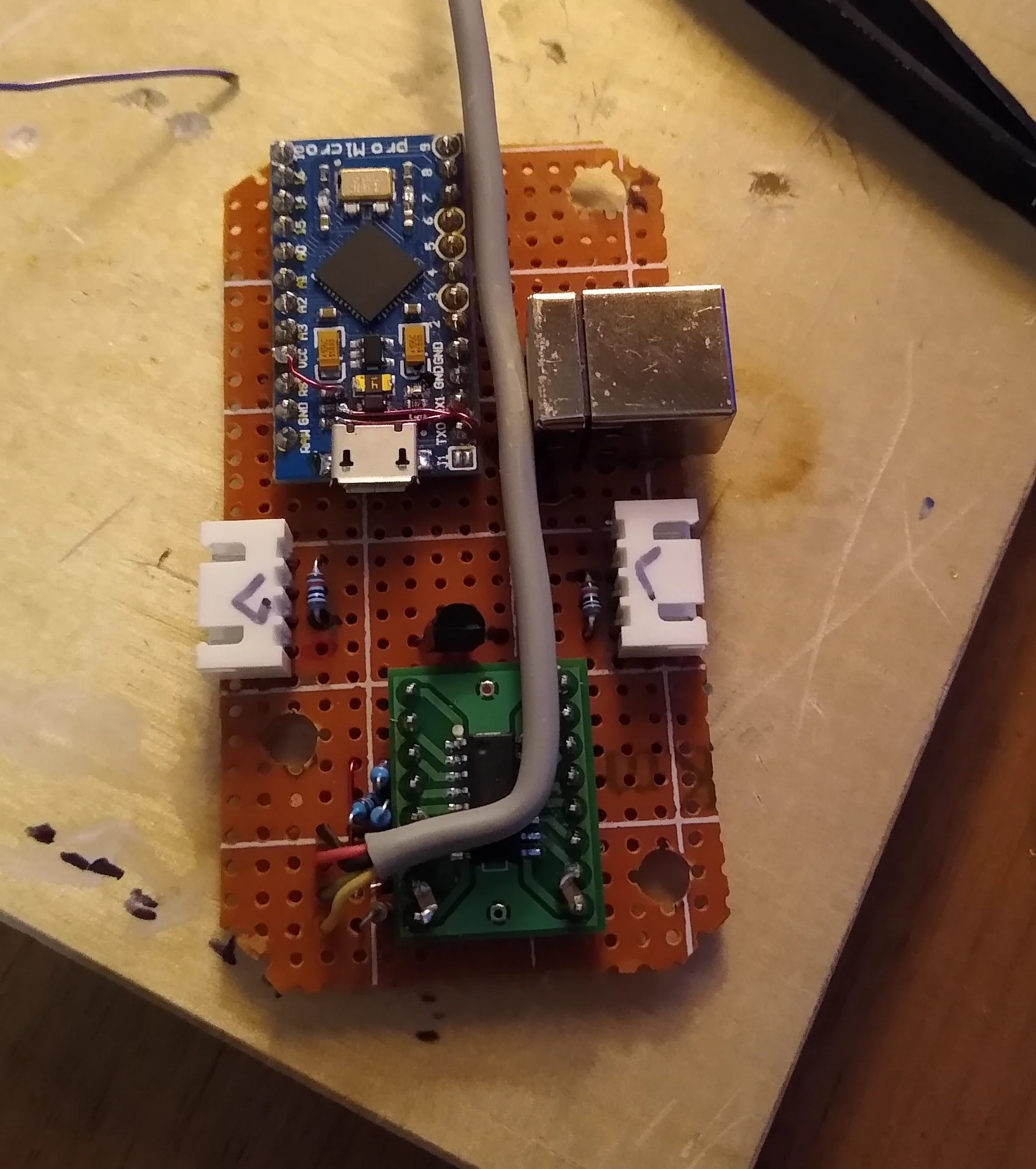
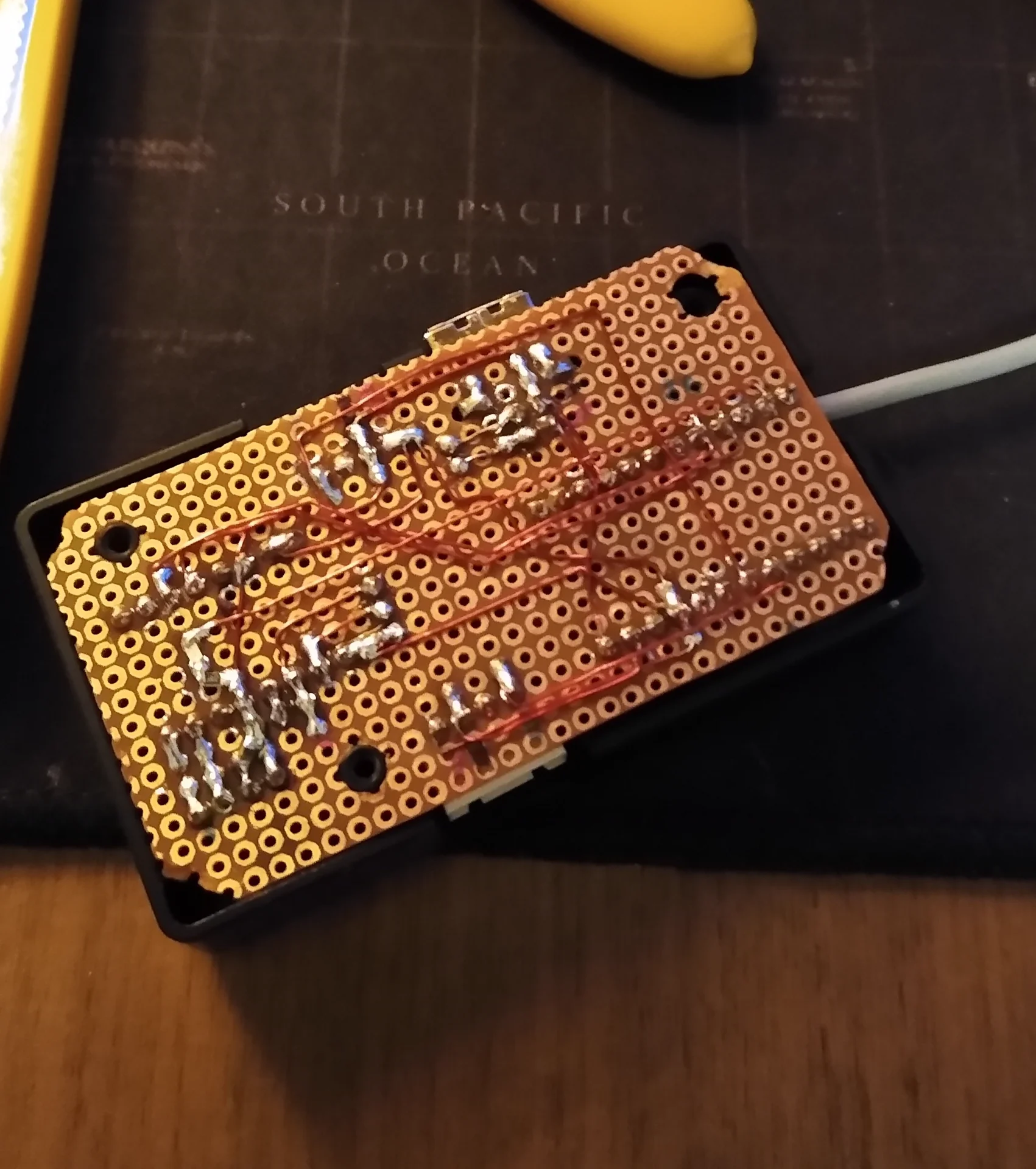
The point-to-point soldering was done using 24 AWG enamel copper wire as it was what I had on hand, and it was easy to remove the enamel. This also gave the board a very nice look when viewing from the bottom.
On the top I used connectors to attach the other two pedals (hall-effect sensor inputs). Additionally, the USB port on the Arduino pro micro board was obstructed, so I "piggy backed" a female USB type-B connector on the board.
Arduino Pro Micro USB 'piggy backing'
To piggy back a USB connection to the Arduino pro micro, I soldered the following connections: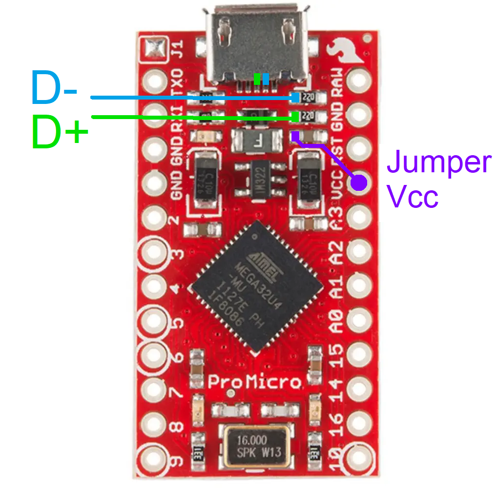
Connecting the D+ and D- to the corresponding pins on the USB type-B connector, and jumping the Vcc pin of the Arduino to the pad of the capacitor (marked in purple in the image).
Given the expedited two-day turnaround, the PCB design was optimized to be reliabile. The resulting boards worked as intended and fit into the pedals effortlessly.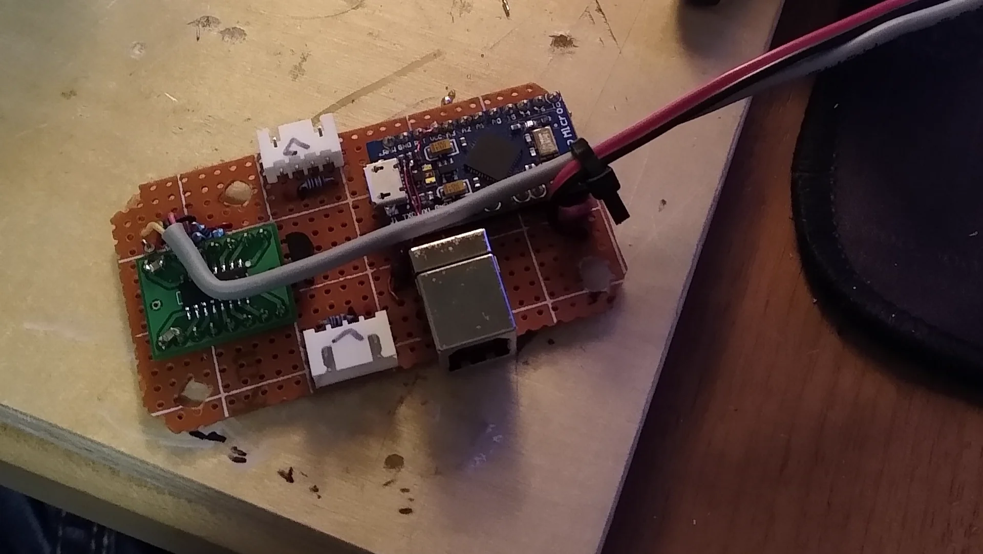
Installation
Putting everything together was quite straightforward, since the mechanical footprint remained the same the only modifications required were swapping out the controller board and replacing the Hall effect sensors.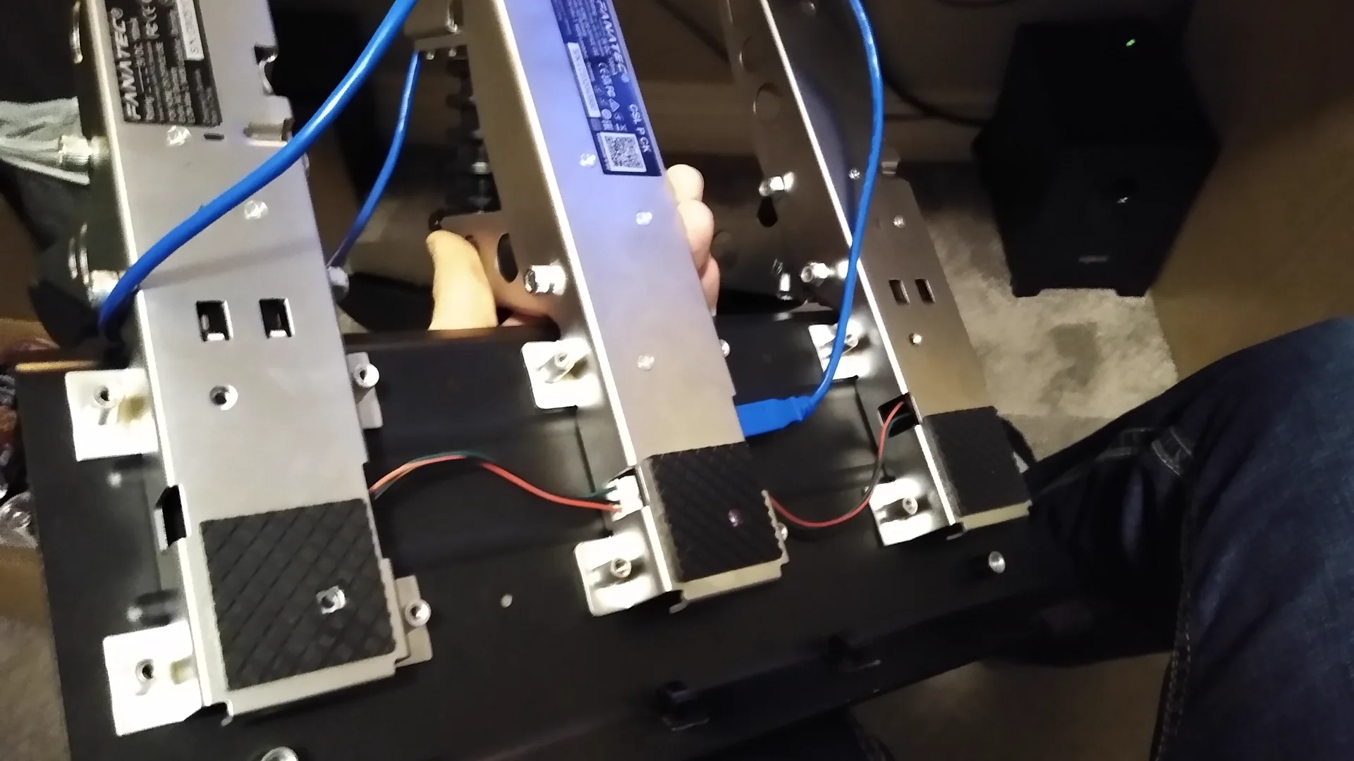
Controller Firmware
The software was written using the Arduino IDE in the C++ language. The libraries I used were joystick.h, HX711.h, and the EEPROM.h library. The ATmega32u4's built in EEPROM was used to save calibration settings.
Startup
When the device powers on, it executes a startup sequence to ensure all hardware components are connected and operable before the main loop begins. The startup sequence is as follows:
- Hardware & Communication Setup
- A 1-second delay is placed at the very start of setup(). This ensures the power rails are completely stable and prevents communication glitches before peripheral initialization.
- The firmware then initializes the joystick object, opens the Serial port for debugging, and connects to the HX711 load cell sensor.
- GPIO & Memory Configuration
- The GPIO pins for the calibration button and the status LED indicator are configured.
- The system reads the saved calibration limits from the EEPROM, allowing the device to retain its accuracy across power cycles without needing a recalibration.
- System Feedback & Diagnostics
- The onboard LED flashes a distinct blink pattern to give a clear visual confirmation that the system booted successfully.
- The retrieved low and high calibration limits are printed to the Serial interface for quick diagnostic verification.
- Boot Guard Interlock
- A final check prevents the main execution loop from starting if the calibration button is held down during boot. This serves as an intentional interlock, allowing the user to trigger a manual calibration sequence before the core application logic takes over.
Libraries, definitions, and Startup() method
#include <Joystick.h>
#include <EEPROM.h>
#include "HX711.h"

#define HX_din 6
#define HX_sck 5
#define led_pin 8

#define deadzoneL 5       // LOWER deadzone with 0-1023
#define deadzoneH 5       // HIGH deadzone with 0-1023
#define LCdeadzoneL 750   // LOWER deadzone with Load Cell
#define LCdeadzoneH 500   // HIGH deadzone with Load Cell

void blinkLED(int pin, int del, double duty, int num) {

	for (int i = 0; i <= num; i++) {
		digitalWrite(pin,HIGH);
		delay(int(del * duty));
		digitalWrite(pin,LOW);
		delay(int(del * (1-duty)));
	}
	digitalWrite(pin,LOW);
}

void setup() {
	delay(1000); 	//Bug Fix

	Joystick.begin();		//Start Joystick
	Serial.begin(9600);		//Start Serial output

	//Start HX711 loadcell amplifier readings 64 or 128 (Channel A hard wired)
	scale.begin(HX_din, HX_sck, 64);
	scale.tare(); // Center Load Cell reading at "zero"


	//Set calibration button input and LED output
	pinMode(9,INPUT_PULLUP);
	pinMode(8,OUTPUT);

	//Load calibration information from EEPROM
	cal_lo_T = intReadEEPROM(0);
	cal_hi_T = intReadEEPROM(2);
	cal_lo_C = intReadEEPROM(4);
	cal_hi_C = intReadEEPROM(6);
	cal_lo_B = longReadEEPROM(8);
	cal_hi_B = longReadEEPROM(12);

	blinkLED(led_pin, 600, 1, 1);

	delay(1000); //Bug Fix

	//Debug Calibration Values
	sprintf(buffer,"T[%.4i, %.4i] \t C[%.4i, %.4i] \t T [%.6ld, %.6ld]",
	cal_lo_T, cal_hi_T,
	cal_lo_C, cal_hi_C,
	cal_lo_B, cal_hi_B
	);
	Serial.println(buffer);

	//If button held down, main loop wont start until let go
  	while (digitalRead(9) == 0);
}
Main Loop
The main loop handles the core runtime logic, which is divided into three primary responsibilities: executing runtime calibration routines, processing and filtering sensor data, and broadcasting the final axis positions to the host PC.
Dynamic Calibration Routine
To ensure long-term accuracy without needing to hardcode sensor values, the firmware includes an on-the-fly calibration routine triggered by the physical calibration button. Calibration Sequence// CALIBRATION SEQUENCE
if (digitalRead(9) == 0) {
while (digitalRead(9) == 0); // wait for button to release
digitalWrite(led_pin, HIGH);
// Set Minimum
cal_lo_T = readADC(A0);
cal_lo_C = readADC(A1);
cal_lo_B = readHXadc();
cal_hi_T = cal_lo_T;
cal_hi_C = cal_lo_C;
cal_hi_B = cal_lo_B;
// Read Maximum input until button press
while (true) {
if (readADC(A0) > cal_hi_T) cal_hi_T = readADC(A0);
if (readADC(A1) > cal_hi_C) cal_hi_C = readADC(A1);
if (readHXadc() > cal_hi_B) cal_hi_B = readHXadc();
//Debug Calibration Values
sprintf(buffer,"T[%.4i, %.4i](%.4i) \t C[%.4i, %.4i](%.4i) \t T [%.6ld, %.6ld](%.4ld) \t %.6ld",
cal_lo_T, cal_hi_T, cal_hi_T - cal_lo_T,
cal_lo_C, cal_hi_C, cal_hi_C - cal_lo_C,
cal_lo_B, cal_hi_B, cal_hi_B - cal_lo_B,
readHXadc()
);
Serial.println(buffer);
if (digitalRead(9) == 0) {
Serial.print("Exit. ");
long t = millis();
while (digitalRead(9) == 0) {
if ((millis() - t) > 800) { // If long press (800ms), save calibration to EEPROM
intWriteEEPROM(0,cal_lo_T); //addr 0-1 (2b int)
intWriteEEPROM(2,cal_hi_T); //addr 2-3 (2b int)
intWriteEEPROM(4,cal_lo_C); //addr 4-5 (2b int)
intWriteEEPROM(6,cal_hi_C); //addr 6-7 (2b int)
longWriteEEPROM(8,cal_lo_B); //addr 8-12 (4b long)
longWriteEEPROM(12,cal_hi_B); //addr 12-14 (4b long)
Serial.print("Saved. ");
blinkLED(led_pin, 400, 0.4, 5);
while (digitalRead(9) == 0);
break;
}
blinkLED(led_pin, 500, 0.6, 2);
}
break;
}
delay(1);
}
}
The sequence executes as follows:
Minimum Bounds: When the button is pressed and released with the pedals at rest, the system captures the baseline sensor values.
Maximum Bounds: The system enters a loop that tracks and retains the highest peak input value as the user depresses each pedal.
Dual-Mode Saving: Upon a second button press, the system checks the hold duration. A short press saves the calibration limits to RAM for temporary testing, while a long press (>800ms) commits the data to non-volatile EEPROM memory.
Data Processing - Mapping, Deadzones, and Clamping
Once raw data is captured from the ADCs and the load cell, the inputs must be conditioned. The raw data is mapped to a standard controller resolution range of 0–1023 while factoring in pre-defined high and low deadzones to eliminate sensor noise at the extremes of pedal travel.
    // Map value between calibration points from 0 to 1023
    unsigned int gasVal    = map(readADC(A0), cal_lo_T +deadzoneL, cal_hi_T -deadzoneH, 0, 1023);
    unsigned int clutchVal = map(readADC(A1), cal_lo_C +deadzoneL, cal_hi_C -deadzoneH, 0, 1023);
    unsigned int brakeVal  = map(readHXadc(), cal_lo_B +LCdeadzoneL, cal_hi_B -LCdeadzoneH, 0, 1023);

    // Clamp value between 0 and 1023
    gasVal    = clamp(gasVal, 0, 1023);
    clutchVal = clamp(clutchVal, 0, 1023);
    brakeVal  = clamp(brakeVal, 0, 1023);
Because the map() function can extrapolate outside the target boundaries if the pedal travel exceeds the calibrated thresholds, a custom clamp() helper function ensures the values stay securely within the 0–1023 bounds to prevent erratic game behavior.
unsigned int clamp(int in, int lo, int hi){
    if (in < lo) in = lo;
    if (in > hi) in = hi;
    return in;
}
Clutch Curve Optimization & PC Output
During testing, a purely linear response on the clutch pedal felt unnatural, making it difficult to modulate the simulated "bite point." To fix this, I implemented a custom piecewise, two-slope response curve.
    if (clutchVal >= 512) {
        clutchVal *= 0.25*((double(clutchVal)/1023)-1)+1;
    } else {
        clutchVal *= 1.75*(double(clutchVal)/1023);
    }
While this mathematical curve does not strictly replicate a physical clutch pressure-to-displacement curve, it heavily skews the output to emulate the subjective "feel" of a real clutch engagement in-game.
Finally, the fully processed data is updated to the PC via the Gamepad API through the Joystick object.
    // Output controller data
    Joystick.setRxAxis(gasVal);
    Joystick.setRyAxis(brakeVal);
    Joystick.setRzAxis(clutchVal);
    delay(1);
Results
Ultimately, the pedals turned out incredibly well for a rapid two-day build. They offer great responsiveness and seamless compatibility across my brother’s favorite games. From a user experience standpoint, the system is entirely plug-and-play—appearing instantly as a standard game controller the moment it is plugged into a PC.
The tight 48-hour timeline pushed me to pick up several new software and hardware skills. Specifically, I gained a lot of hands-on experience working with the ATmega32u4’s native USB HID functionality to implement the game controller architecture, and I learned how to successfully piggyback an additional USB plug onto the Arduino Pro Micro.
Moving forward, the platform is highly adaptable. The underlying code can easily be reprogrammed down the road to support new titles, advanced input curves, or entirely new functionalities.