Recently, I have been designing a superheterodyne receiver for the 20m amateur radio band. As an interim milestone, I integrated the currently completed stages to temporarily operate the system as a direct conversion receiver.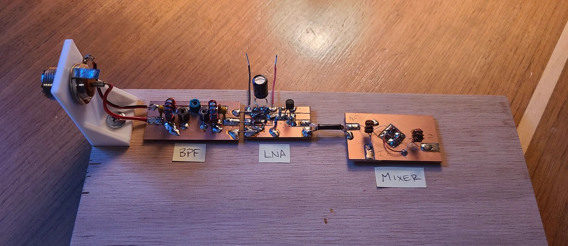
Radio Components
A DCR simplifies reception by mixing the incoming RF signal with a local oscillator (LO) tuned to the exact same target frequency. This 'zero-IF' approach downconverts the radio signals directly into baseband audio, completely bypassing the need for intermediate frequency stages and allowing me to instantly evaluate my front-end gain and LO stability.
Overview
The basic DCR block diagram shows how a small number of building blocks can be used to create a radio reciever. I set out to build each of these building blocks from elementary electronics parts.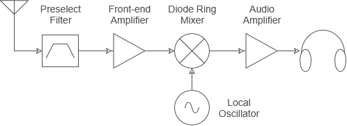
I built this radio by designing and making three of its core components from scratch. Because each component came with its own set of hurdles, I’ve written blog posts covering the design process and challenges for each one.
The components I built for this project were:
Band Select Filter
The band select filter is a bandpass filter designed to isolate the desired frequency band that you wish to recieve to. In the case of this reciever, the bandpass filter was designed for the 20m amateur radio band which exists between 14.00 MHz and 14.35 MHz.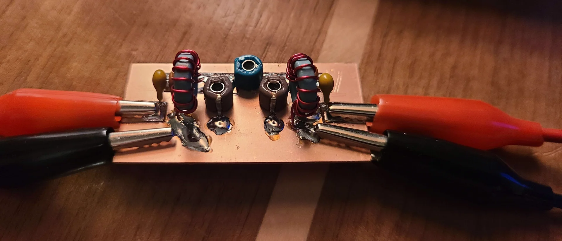
Measuring the filters S11 and S21 response with the NanoVNA, an insertion loss of 1.19 dB over a bandwidth slightly wider than the 20m band was measured.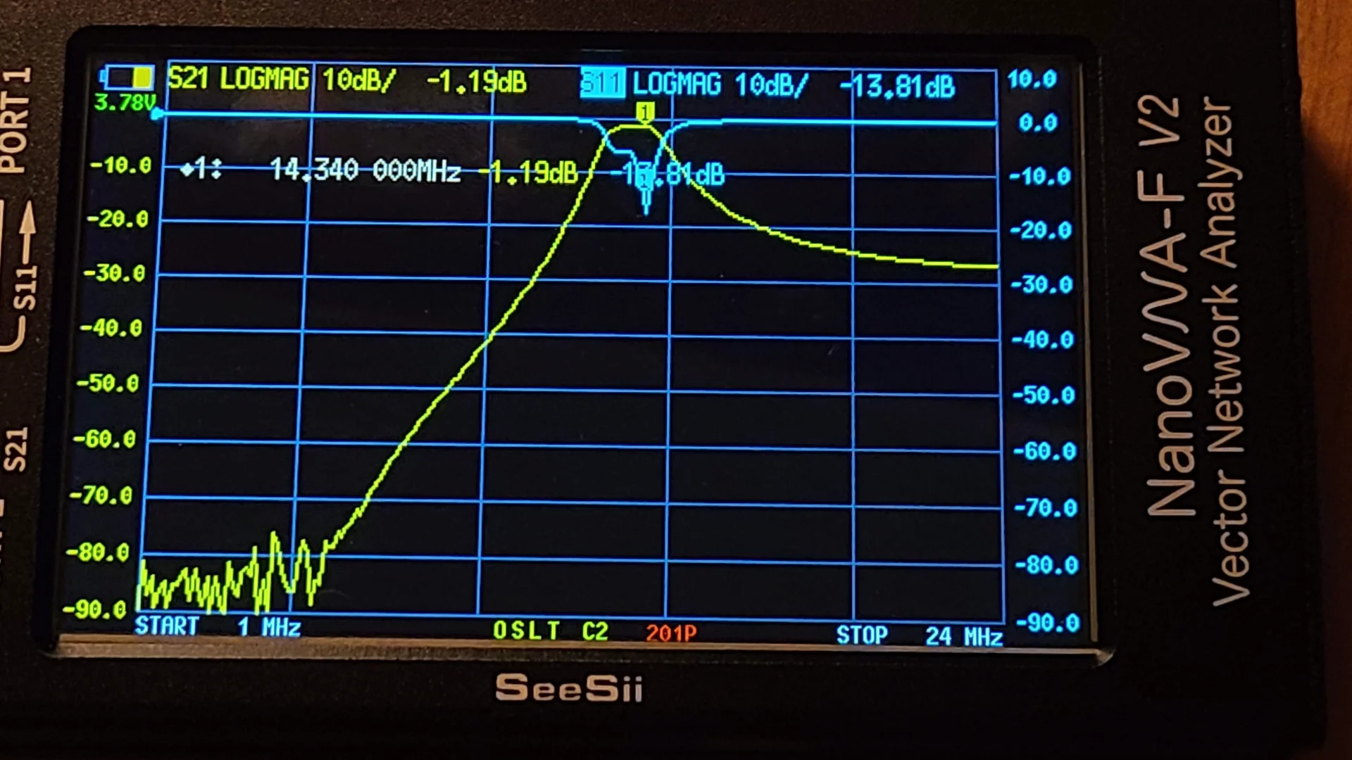
Frontend Amplifier
The frontend amplifier is designed to amplify the incoming signals and condition them for the diode ring mixer. The amplifier was designed to be in a cascode configuration to achieve high gain, lower noise figure, and moderate to low input impedance.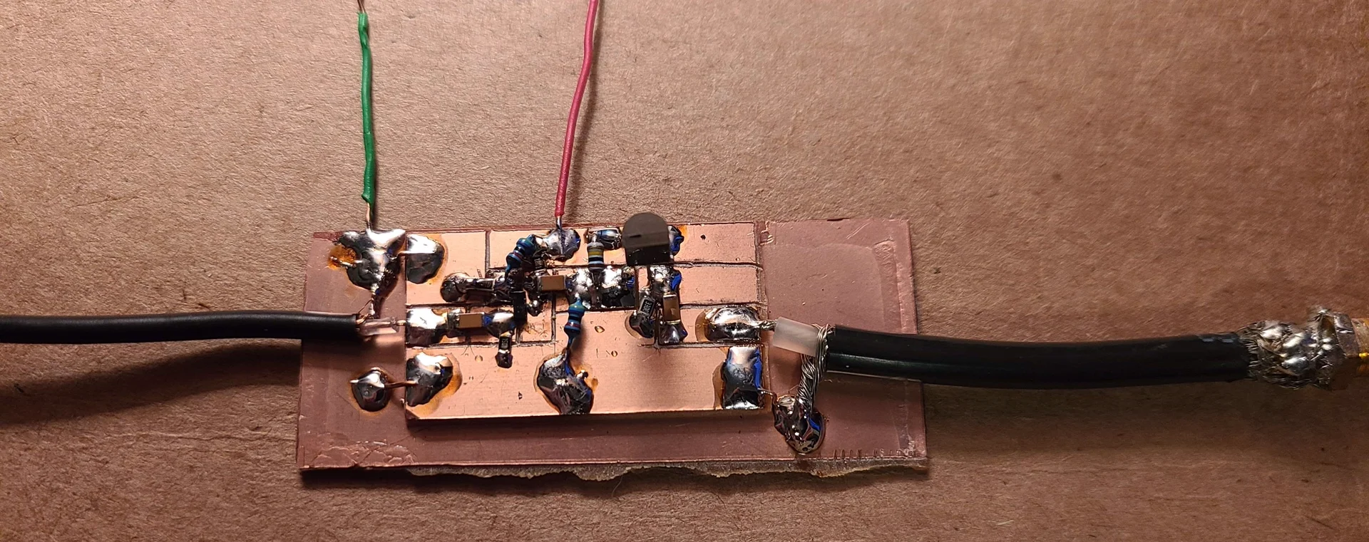
Connecting the amplifier to the function generator and oscilloscope, a gain of 22.8 dB was measured.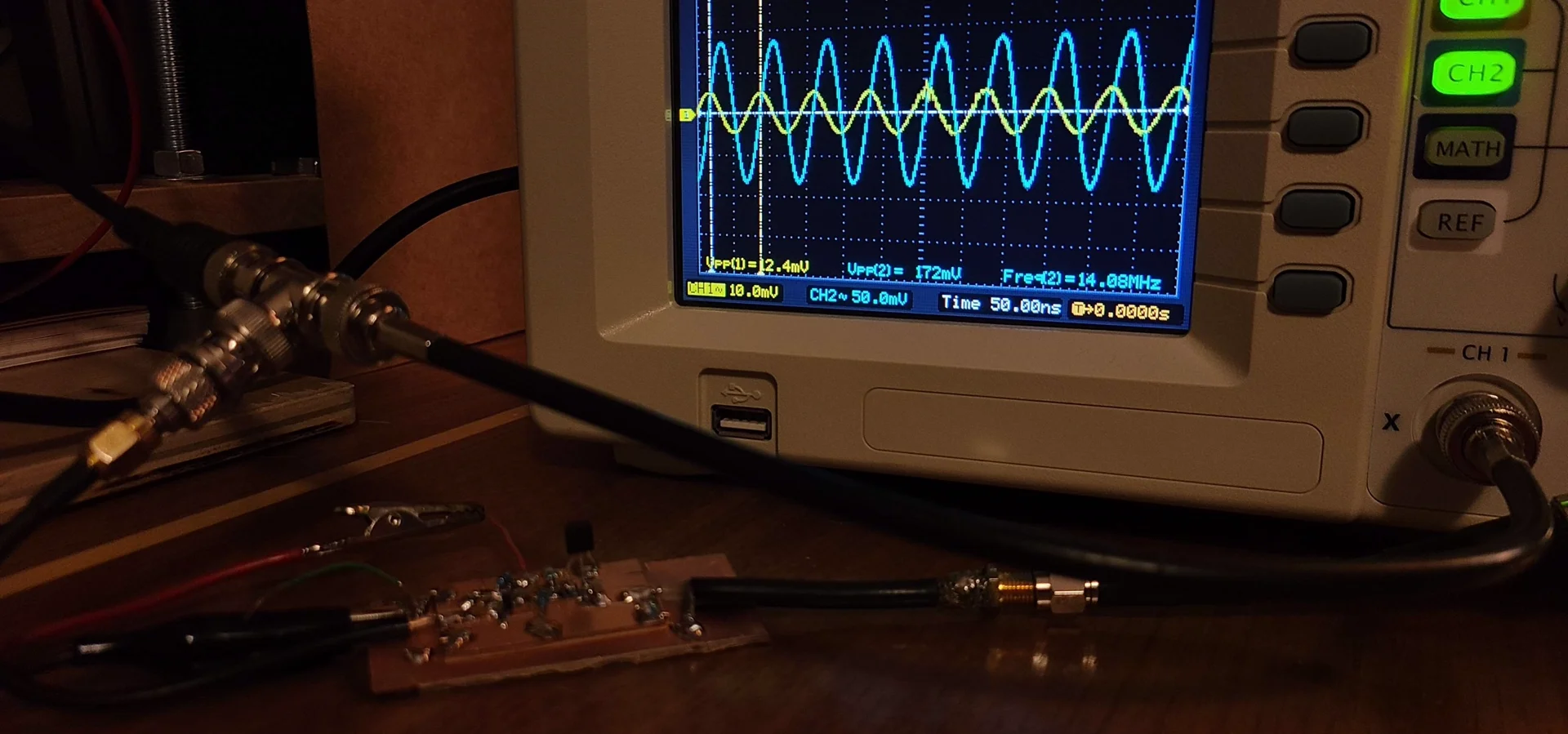
Diode Ring Mixer
The defining component of any radio receiver is the mixer, which multiplies incoming signals to produce both the sum and difference of two input frequencies. The diode ring mixer achieves this by using a LO to drive diodes on and off, effectively chopping the incoming signal. I constructed this specific component using off-the-shelf diodes.
Using a 14 MHz input signal and a 5 MHz LO signal, I measured the output of the mixer using my TinySA spectrum analyzer.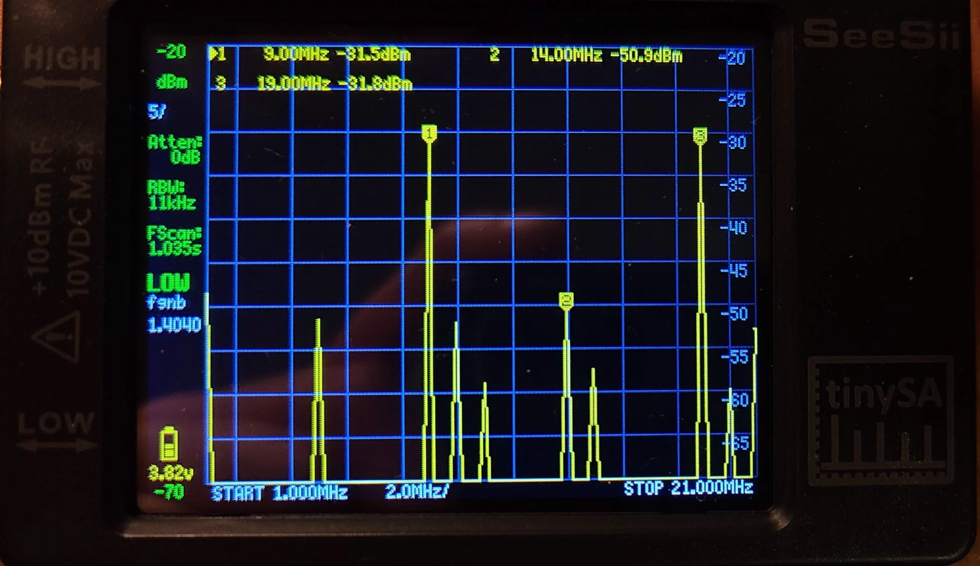
Fully Assembled Radio
The radio was assembled and tested using my 20m band dipole antenna outside. The reciever was capable of picking up amateur radio operators transmitting single sideband (SSB) voice transmissions and morse code. I used my function generator as the LO, and used an op-amp audio amplifier circuit I put together on a breadboard.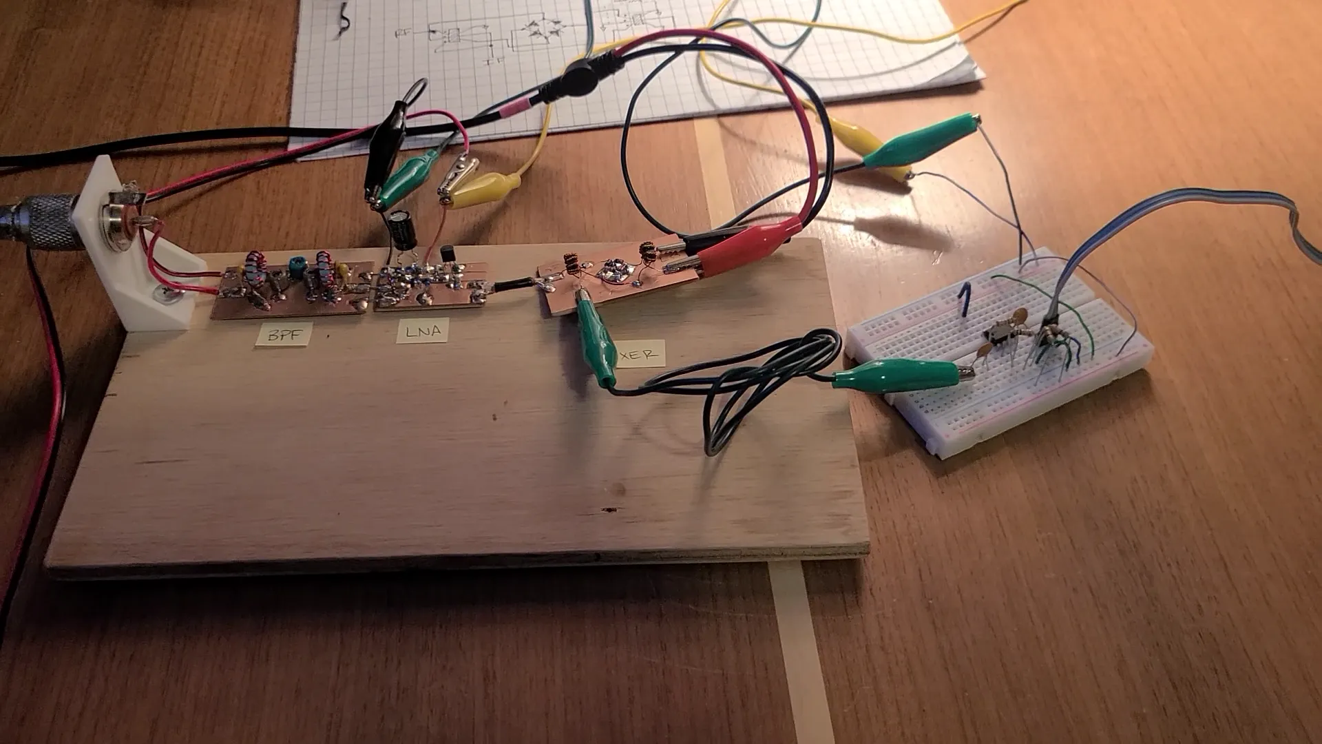
Results & Videos
The reciever had some noise or oscillations occurring internally which I believe is from a poor termination on the diode ring mixer. Diode ring mixers are notoriously picky about terminations.
The first signals I was able to listen to were some amateur radio operators out of North Carolina and Ohio.
I also recieved the 15MHz NIST Clock signal (Station WWV) transmitted near Fort Collins, Colorado.