In the autumn of 2025, I once again volunteered to create and present a printed circuit board (PCB) design workshop for the University of British Columbia Okanagan's (UBCO) IEEE McNaughton Learning Resource Center's (MLRC) Hackerspace (or UBCO IEEE MLRC Hackerspace for "short").
Having hosted this workshop in 2022 and 2023, I knew how I could improve this workshop even more.
In the 2023 EWorkshop I recieved feedback that the PCB was difficult for beginners who have never soldered before which I should have expected since I chose to use SMD components for the PCB.
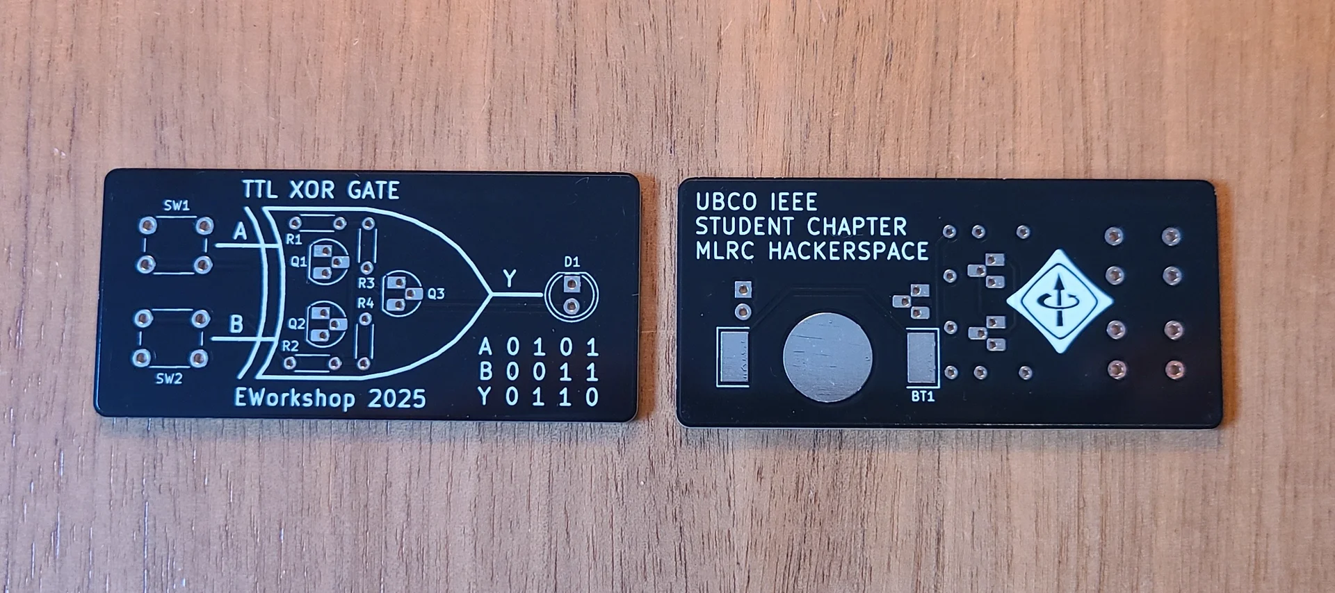
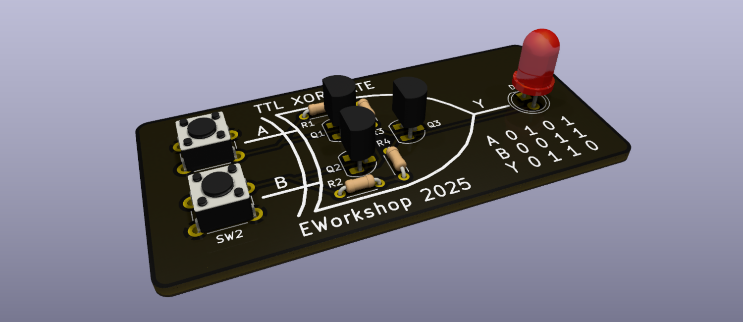
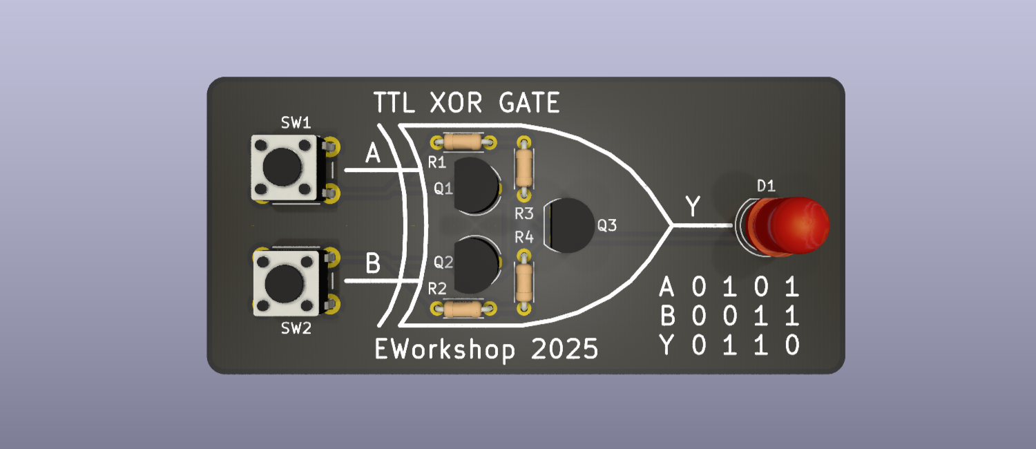
This year I decided to go with a different PCB design. One that is simpler, is made with through hole components, and has fewer parts, all while being tactile and captivating. The board was based on a transistor-transistor logic (TTL) exclusive OR (XOR) gate. Using 3 BJTs, 4 resistors, 2 SPST push buttons, and an LED.
Before going into the circuit however, I will cover how I structured the workshop.
Presentation and Structure
The presentation structure was similar to the 2023 workshop. I primarily covered the following:
- Introduction to the KiCAD software - A brief run through of the project creation process.
- Introduction to the schematic editor, placing components, changing and adding component properties.
- Sourcing parts from sites like DigiKey and Mouser.
- Generating a bill of materials (BOM)
- Configuring the PCB editor, setting DRC tolerances, importing footprints, and PCB layout.
- Running design rule checks on the final PCB design and exporting gerber (manufacture) files.
- Ordering PCB's from sites like OSH Park, PCBway, and JLCPCB.
On later dates, students could also come to the hackerspace to learn how to solder the PCBs.
Like I mentioned in 2023 EWorkshop, the information from the schematic design best practice and PCB design best practice to my notes section of my site which has my updated and most recent personal best practices that I employ.
Documents
I reused most of the presentation structure from the 2023 workshop, and adjusted it to have information on the new circuit.
The supplimental documents I made for the 2023 workshop still apply to this workshop, so I gave them a touch-up and provided them to students.
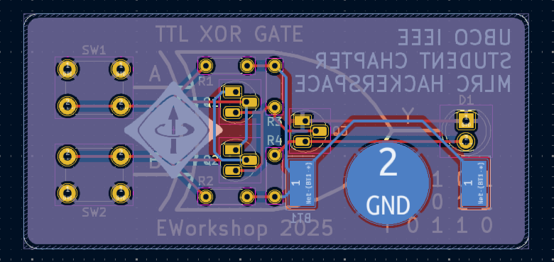
Circuit and PCB
The circuit I chose to use was a TTL XOR gate, consisting of a few BJTs, resistors, buttons, and an LED.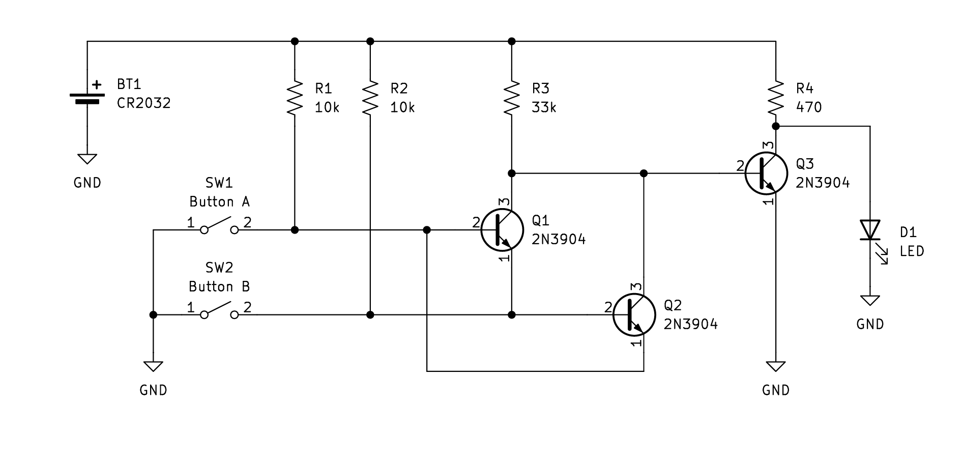
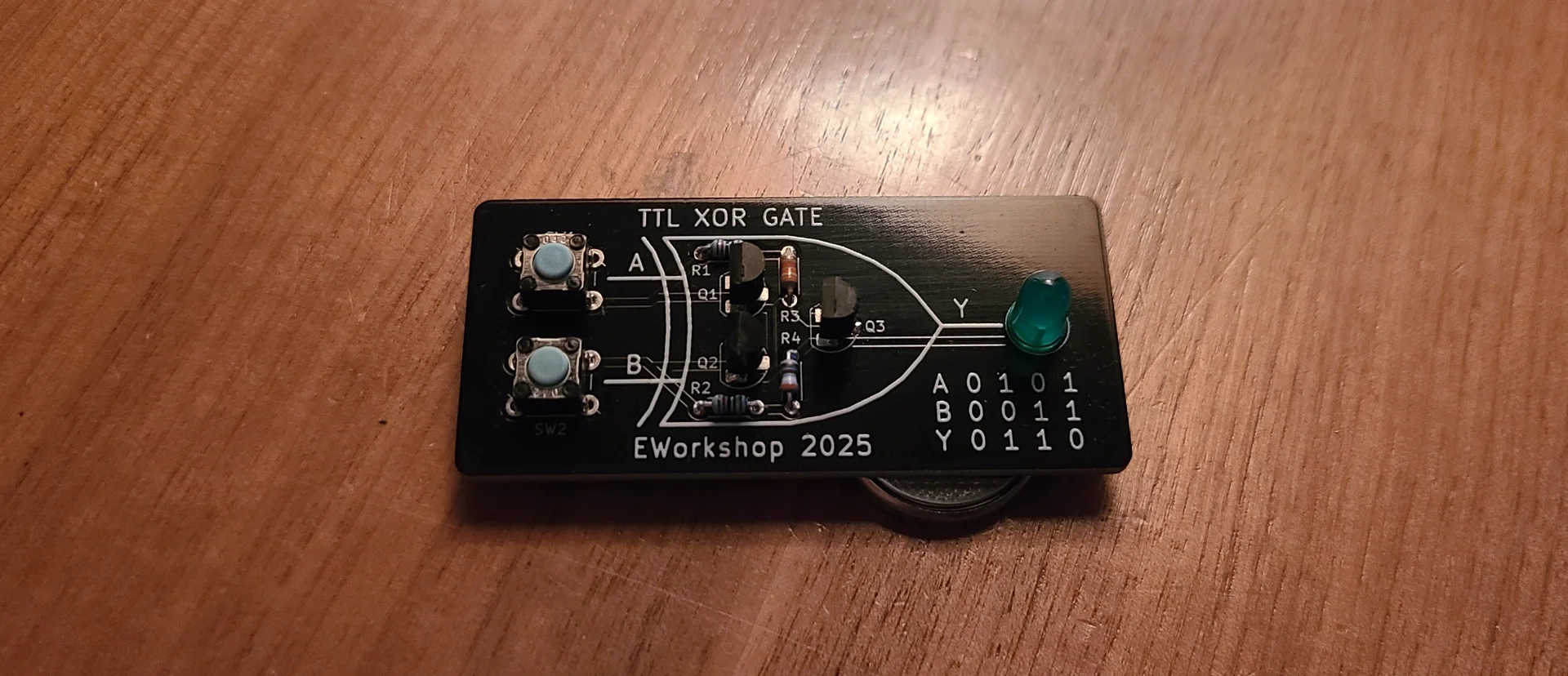
Before I designed the PCB, I made sure to prototype the circuit to verify that it is functional.
Once the circuit was prototyped and validated, I designed the PCB.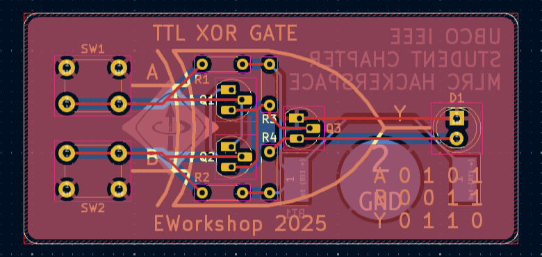
Workshop Event
This workshop had a large turnup, with students in different areas of study such as Computer Science, Computer Engineering, Mechanical Engineering, and Electrical Engineering. Presenting the workshop, we covered all the basics of KiCad and I had time to spare in the third session to answer any additional questions that attendees had.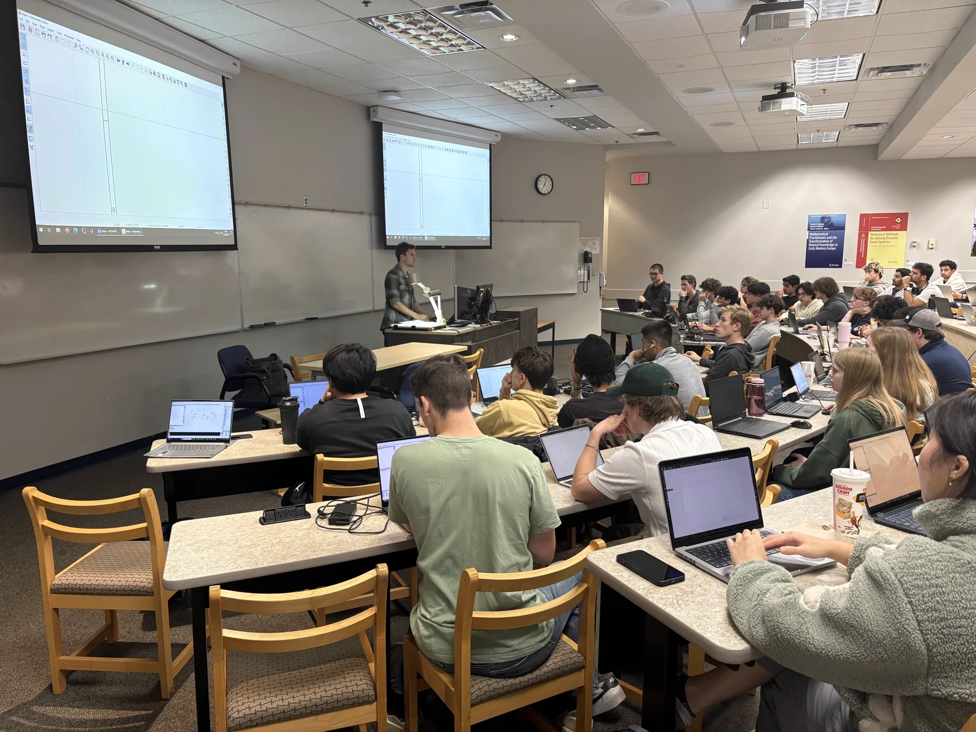
Final PCB